background image

20

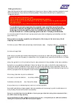
WARMUP

600s

With power applied the system should undertake its power up sequence and 

then commence a warm up period. The warm up period is there to allow 

connected detectors to stabilise before operation. Note that certain detector 

types, Oxygen sensors in particular may take up to 2 hours to fully stabilise.

During the warm up period check that each connected detector or device has power and 

communication. The following diagram shows the three main terminal PCB types for detectors and I/O 

interface nodes and the relevant check points.

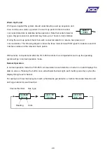
Warm Up Period

In normal operation mode the TOC-650 communicates to each detector or node in turn and displays the 

data on screen. Pressing the button once will activate the back light, each button press then cycles the 

display through each channel.

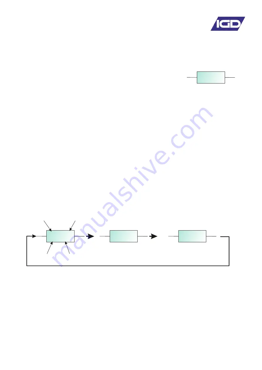
For example a three channel system with a Flammable gas detector, a Carbon Monoxide Detector and 

an Oxygen detector would read as:

With sensors connected and after the TOC-650 controller has completed its warm up the operating 

system will go to normal operation mode.

Normal Operation

1=FLAM
0% LEL

2 = CO

0 ppm

3 = O2

21% VOL

Channel Number      Gas Type

Reading         Units

Summary of Contents for TOC-650-150

Page 1: ...r a t i o n a n d M a i n t e n a n c e V 3 1 Triton House Crosby Street Stockport Sk2 6SH England T el 44 0 161 483 1415 Fax 44 0 161 484 2345 Email sales internationalgasdetectors co uk Website www...

Page 2: ...10 4 14 5 7 12 23 27 27 Addressable Detector Node Highway Hub Controller Overview Relay Card Overview Relay Card Setup User Actions Overview Menu overview Putting Into Service New Setup Sequence The S...

Page 3: ...aster Salve Brief Introduction Jog Wheel Interface Service Maintenance The Control Panel leaves the factory configured for the supply voltage stated on the customers order Should the control panel be...

Page 4: ...0V AC 50 60Hz by selection 1 LEL 2 x 8 LCD Display and Jog Wheel 0 1ppm Full EC Declaration appears on Page 4 0 to 55 Degrees Centigrade IP ratings do not imply that the equipment will detect gas duri...

Page 5: ...aratus using software and or digital technologies Excluding requirements for SIL EMC Generic standards Immunity for industrial environments Electrical apparatus for the detection and measurement of fl...

Page 6: ...which supplies gas at 0 5L Min Important Notes Panel Options TOCSIN 750 Series Controller TOCSIN 750 Series Annunciator Options With Display Relay Output Digital or Analogue Input Flammable Gas Detect...

Page 7: ...tem cables must be screened refer to installers guide General Power can be taken from system modules for small current devices such as LED beacon sounders and is limited to 100mA per module Highways a...

Page 8: ...this document prior to installation 2 WIRE SYSTEMS 2 W i r e G a s D e t e c t i o n S y s t e m I n s t a l l e r s G u i d e V x x OLIVER IGD Triton House Crosby Street Stockport SK2 6SH England T...

Page 9: ...upporting 32 Devices 128 Devices in Total Two display options either 650 style with jog wheel or HMI Style touch screen display Note both displays can be tted at the same time which can allow the HMI...

Page 10: ...DOWN BUTTON UP BUTTON Each Addressable relay card must have its own unique base address This can be set on the card and is indicated below The relays are then addresses numbered from that base address...

Page 11: ...this one Base Address set up LED s and interface for the relay card In all Cases Relay contact ratings 5A 250V AC Non Inductive 5A 30V DC Non Inductive Spike suppression must be fitted Note that FAULT...

Page 12: ...nalogue and digital inputs that can be used to read data onto the system from external devices Setup of the inputs type range addressing etc is controlled via IGD s Android Apps Wiring options are ind...

Page 13: ...put DVM Test Point DVM Test Point Housing Sealing Environment Temperature Voltage Communication Display Analogue I P Sounder Digital Input Relay Pellistor Port Digital Output Comm Port 2 3 4 5 6 7 1 S...

Page 14: ...threshold it will not be possible to reset the alarm Once fully installed the TOC 650 controller will continuously monitor connected gas detectors and sensors and compare current values with any set a...

Page 15: ...D Red Continuous on Alarm Level 2 Flashes on Alarm Level 1 Power LED Green Selector Button Selector Jog Wheel WARMUP 600s o Indicate board tested status end user should see PASSED with a green backlig...

Page 16: ...ement With the correct password displayed press the centre selection button to go to the menu or function Current Channel Reading Inhibit the control panel for up to 60 minutes Use this option if cali...

Page 17: ...Use this option to FIND Relay Outputs Use to Access Device Diagnostics Set the System Time Set the System Date Move to the USER 100 Menu Use to enable Disable Reset Bluetooth Use to Energise De energ...

Page 18: ...8 ENG MENU 7 of 8 EXIT 8 of 8 Production Menu Options Provides access for control panel set up and diagnostic functions Use this option to Reset the Hubcard System Re boot Reset Hubcard to defaults Di...

Page 19: ...Menu CALibrate Note IGD calibration and gas adaptor kits are available and necessary to perform calibration and bump testing Record all results for traceability find sen 1 of 12 find rly 1 of 12 zero...

Page 20: ...for detectors and I O interface nodes and the relevant check points Warm Up Period In normal operation mode the TOC 650 communicates to each detector or node in turn and displays the data on screen Pr...

Page 21: ...ed Check the shipping TOC 650 SET UP REPORT to check how the controller and interfacing detectors and nodes have been configured Ensure that the detector addresses match the document and required site...

Page 22: ...he following manner Press and hold button until prompted to release The system starts discovering connected devices Display indicates devices found so far Display indicates progress When the discovery...

Page 23: ...ro gas and zero the channel observe and record result Notes All gas detectors will require periodic ZERO and CALIBRATION The calibration interval depends on a number of environmental factors such as t...

Page 24: ...e is no gas present by using a portable detector B Use a suitable ZERO gas as follows Zero gas should have a humidity between 0 90 RH O2 CO2 NITROGEN PELLISTOR INSTRUMENT AIR TOXIC GASES NITROGEN The...

Page 25: ...erate This type of alarm is typically used in safety applications for Oxygen deficiency monitoring where you are monitoring for a falling Oxygen level Press and hold until prompted to release to selec...

Page 26: ...t a zero or calibration the controller sends the request to the detector head for action and monitors the result This means that detectors can be supplied pre calibrated The reading is now displayed s...

Page 27: ...Calibrate zero point Standard accessories Supplied 1 x Terminator Set 5 off 1 x Diode Pack 1 x Snubber 1 x Resistor Pack Battery Care Installation The batteries will come pre installed but will be di...

Page 28: ...ter Disk 5110101 Remote Gassing Port 5134601 40mm Stop Button 5138601 Collector Cone Ring Lock 5138701 T103 Splash Guard 5138801 Collector cone kit MK6 TOC GLAND M20 Snap fit cable glad 5925801 Univer...

Reviews: