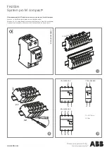
background image

3

UK

3  Installation


► Mount the devices on a 35 mm rail.

1

2

3

4

Example DF22xx circuit protection module
1:  rail

2:  contact lever

3:  installation area

4:  operating area

4  Electrical connection


► Dimension cables according to input and output current.


► Insert wires directly into the terminals as shown on the device label.

Art. no.

Terminals

Potential

Cross-

section  

[mm²]

Stripping 

length  

[mm]

DF21xx

24 V DC

supply

0.5...10

18

0 V

0.14...2.5

8...10

L+, C/Q, L-

IO-Link

0.25...0.5

6

DF22xx

O1 or O1/O2

current outputs

0.14...2.5

8...10

To disconnect press the orange pusher using a suitable tool.
To open the push-in terminals IO-Link use a 2 mm wide micro screwdriver.

Summary of Contents for DF21 Series

Page 1: ...Installation instructions Electronic circuit breakers IO Link for the 24 V DC secondary circuit DF21xx DF22xx 80278886 00 10 2018 UK...

Page 2: ...e matching circuit protection modules Observe the technical data of the circuit protection modules used The devices must be installed connected and put into operation by a qualified electrician Adhere...

Page 3: ...input and output current Insert wires directly into the terminals as shown on the device label Art no Terminals Potential Cross section mm Stripping length mm DF21xx 24 V DC supply 0 5 10 18 0 V 0 14...

Page 4: ...status LED channel 2 3 ON OFF reset button and status LED channel 1 4 push in terminals outputs 1 2 5 1 DF21xx supply modules Status LED Operating mode IO Link communication off missing operating vol...

Page 5: ...switched off Cyclic data exchange is not possible acyclic data exchange is conditionally possible After the device has received the valid configuration and parameter data it quits this operating mode...

Page 6: ...red once The status LED flashes orange to display the set nominal current The LED Flashes red once to confirm completion of the cycle The LED flashes orange once or multiple times in accordance with...

Page 7: ...ECClass2 Inputcurrent max totalcurrent A 40 Numberofchannels 1 2 NominalcurrentIN fail safeIN A 8 8 10 10 2 2 4 4 6 6 3 1 10 16 Mechanicaldata Installation Devicewidth mm Ambienttemperature C Storaget...

Page 8: ...ective circuit protection module and the respective wire cross sections 7 IO Link The load current warning threshold can be configured via the IO Link inter face to provide a visual warning and a warn...

Reviews: