background image

PEB-7605 Series User’s Manual   


31


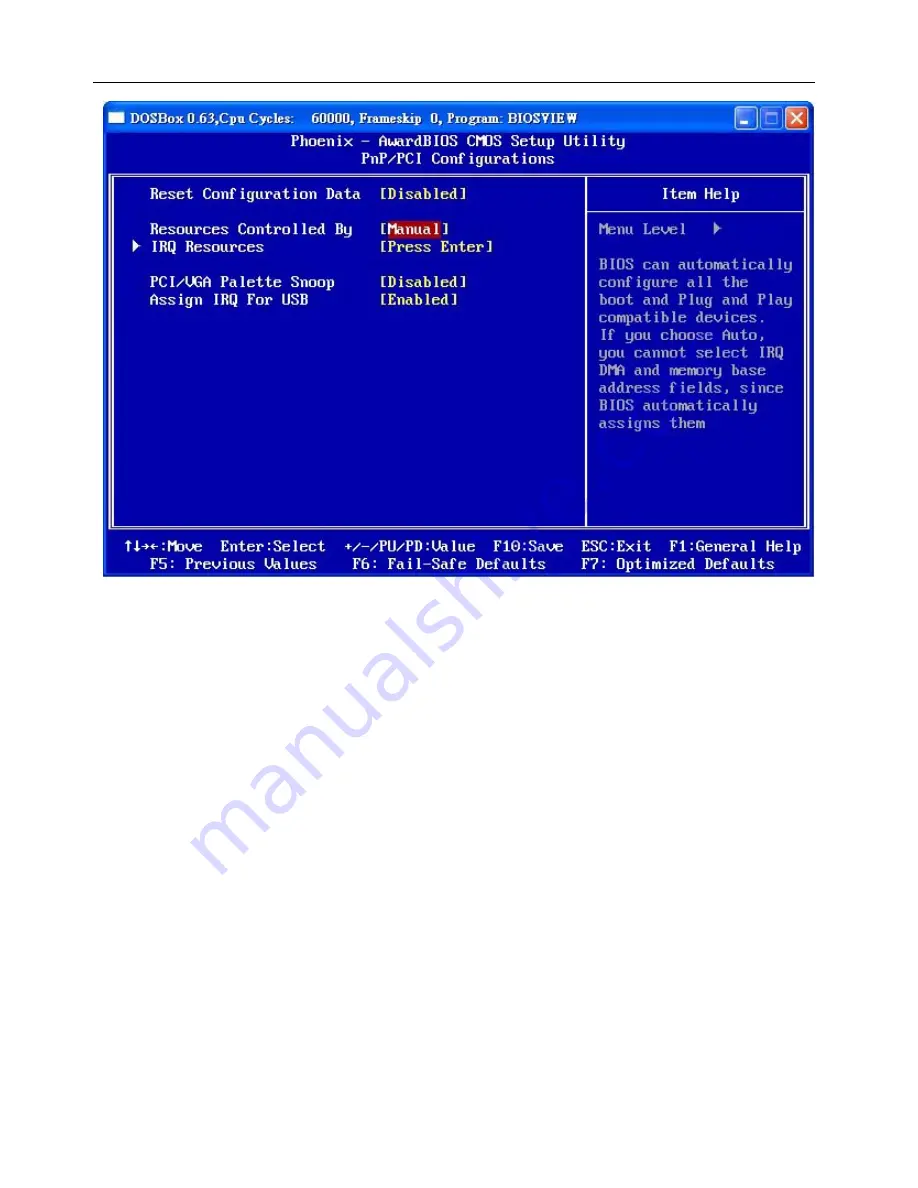
Reset Configuration Data 

If you just install a new hardware or modify your computer

s hardware configuration, the BIOS will automatically detect the 

changes and reconfigure the ESCD(Extended System Configuration Data). Therefore, there is usually no need to manually force 
the BIOS to reconfigure the ESCD. However, the occasion may arise where the BIOS may not be able to detect the hardware 
changes. A serious resource conflict may occur and the operating system may not even boot as a result. This is where the Reset 
Configuration Data BIOS feature comes in. This BIOS feature allows you to manually force the BIOS to clear the previously 
saved ESCD data and reconfigure the settings. All you need to do is enable this BIOS feature and then reboot your computer. 
The new ESCD should resolve the conflict and allow the operating system to load normally. Please note that the BIOS will 
automatically reset it to the default setting of Disabled after reconfiguring the new ESCD. So, there is no need for you to 
manually disable this feature after rebooting. 

Resources Controlled By 

This BIOS feature determines if the BIOS should automatically configure IRQ and DMA resources. The BIOS is generally 
capable of automatically configuring IRQ and DMA resources for the devices in your computer. Therefore, it is advisable that 
you set this feature to 

Auto

. However, if the BIOS has problems assigning the resources properly, you can select the 

Manual


option to reveal the IRQ and DMA assignment fields. You can then assign each IRQ or DMA channel to either 

Legacy ISA

 or 

PCI/ISA PnP

 devices. 

Legacy ISA

 devices are compliant with the original PC AT bus specification and require a specific 

interrupt and/or DMA channel to function properly. 

PCI/ISA PnP

 devices, on the other hand, adhere to the Plug and Play 

standard and can use any interrupt or DMA channel. 

4.8.1  IRQ Resources 

When resources are controlled manually, you can assign each system interrupt a type, depending on the type of device using the 
interrupt. This is only configurable when “

Resources Controlled By

” is set to “

Manual

”.  

Options: IRQ-3/ 4/ 5/ 7/ 9/ 10/ 11/ 12/ 14/ 15 assigned to PCI device 


Summary of Contents for PEB-7605 Series

Page 1: ...ocket 478 479 Pentium M Celeron M Mini ITX Main Board User s Manual P N PEB 7605 Version 1 0 July 28 2006 Copyright Jun 2002 All rights reserved All other brand names are registered trademarks of their respective owners ...

Page 2: ...DS2 LCD Panel Connector 12 2 2 18 LVDS Panel PWR Connector 12 2 2 19 Inverter PWR Connector 13 2 2 20 Compact Flash Connector 13 Chapter 3 System Installation 14 3 1 Socket 478 479 Processor 14 3 1 1 Installing Pentium M Celeron M CPU 14 3 1 2 Installing Processor FAN Cooler and Heat Sink 14 3 1 3 Main Memory 15 3 2 Installing the Mini ITX M B 15 3 2 1 852GM Integrated Graphics controller 15 3 2 2...

Page 3: ...PEB 7605 Series User s Manual 2 4 13 Load Fail Safe Defaults 35 4 14 Load Optimized Defaults 35 4 15 Save Exit Setup 36 ...

Page 4: ...verview of the product specifications and basic system architecture for the PEB 7605 server board Chapter 2 Hardware Configuration Setting shows the definitions and locations of Jumpers and Connectors so that you can easily configure your system Chapter 3 System Installation describes how to properly mount the CPU main memory and M System Flash disk for a safe installation It will also introduce a...

Page 5: ...multi mode parallel port supports SPP EPP ECP function three RS 232 serial port interface and one RS 232 pin herder Besides H W monitor function Intel High Definition Audio as 5 1 surround sound Hi Speed USB 2 0 x 6 ports offer up to 40X greater bandwidth over USB 1 1 Also provide dual display function by VGA and LVDS interface The Mini ITX standard makes the PEB 7605 SERIES work with the one slot...

Page 6: ...use Auxiliary I O One 2 pin system reset switch One 2 pin system power on LED One 2 pin HDD active indicator interface One 2 pin ATX power control interface Two 3 pin headers for CPU and system fan Real Time Clock Calendar RTC Build in ICH4 Y2K compliant System Monitoring and Protection Monitoring system temperature voltage and cooling fan status Auto throttling control when CPU overheats System a...

Page 7: ...h Power Requirements 5V 165mA typical 12V 405mA 12V 61mA 3 3V 2 82A Operating Temperature 0 60 Storage Temperature 20 70 Relative Humidity 5 to 95 non condensing 1 3 System Architecture All of details operating relations are shown in Figure 1 1 PEB 7605 SERIES System Block Diagram Figure 1 1 PEB 7605 SERIES System Block Diagram ...

Page 8: ... general jumpers on the Mini ITX are used to select options for certain features Some of the jumpers are designed to be user configurable allowing for system enhancement The others are for testing purpose only and should not be altered To select any option cover the jumper cap over SHORT or remove NC it from the jumper pins according to the following instructions Here NC stands for Not Connect 2 2...

Page 9: ...g COM1 COM2 ring function 2x5 shrouded header JP2 Setting COM3 COM4 ring function 2x5 shrouded header AUDIO1 AUDIO interface 2x5 shrouded header ATX_PWR 20 PIN ATX Power connector 2x10 power connector VGA DUB 15 port VGA connector LVDS Dual Channel 24 bit LVDS Hirose DF13 20DP LCD Inverter LVDS Inverter power voltage Hirose DF13 9DP LVDS_PWR Setting LVDS power voltage 1x3 shrouded header IDE0 IDE0...

Page 10: ...und 8 PW_OK 9 5V SB 10 12V 11 3 3V 12 12V 13 Ground 14 PS ON 15 Ground 16 Ground 17 Ground 18 5V 19 5V 20 5V PIN No Signal Description 1 Data Carrier Detect 2 Received Data 3 Transmit Data 4 Data Terminal Ready 5 Ground 6 Data Set Ready 7 Request To Send 8 Clear To Send 9 Ring Indicator 10 Not used PIN No Signal Description 1 GPIO 32 2 GPIO 36 3 GPIO 33 4 GPIO 37 5 GPIO 34 6 GPIO 38 7 GND 8 GND ...

Page 11: ...ining the USB ports is attached to the computer casing Note If you are using a USB 2 0 device with Windows 2000 XP you will need to install the USB 2 0 driver from the Microsoft website If you are using Service pack 1 or later for Windows XP and using Service pack4 or later for Windows 2000 you will not have to install the driver Pin Signal Description Pin Signal Description 1 STB 2 D0 3 D1 4 D2 5...

Page 12: ...fault is 7 9 8 10 short 2 2 12 Audio function for external 2 2 12 1 Audio Jack 2 2 13 CF_PWR Default is 1 2 short be 3 3V Pin Assignment Pin Assignment 1 TX 5 NC 2 TX 6 RX 3 RX 7 NC 4 NC 8 NC Pin Assignment Pin Assignment 1 5 5 V fused 3 7 USBP0 P1 2 6 USBP0 P1 4 8 Ground PIN No Signal Description 1 VCC5 2 VCC5 3 XNR11 4 XNR12 5 VCC12 6 VCC12 7 XNR11 8 XNR12 9 NR11 10 NR12 PIN No Signal Descriptio...

Page 13: ...ion 1 Keyboard Data 2 Mouse Data 3 Ground 4 5V 5 Keyboard Clock 6 Mouse Clock PIN No Signal Description 1 Red Signal 2 Green Signal 3 Blue Signal 4 NC 5 GND 6 GND 7 GND 8 GND 9 VCC 10 GND 11 NC 12 DCC_DATA 13 HSYNC 14 VSYNC 15 DCC_CLK PIN No Signal Description PIN No Signal Description 1 VCC 2 VCC 3 VCC 4 VCC 5 YAM0 YBM0 6 YAM3 YBM3 7 YAP0 YAP0 8 YAP3 YBP3 9 GND 10 GND 11 YAM1 YBM1 12 CLKAM CLKBM ...

Page 14: ...HD06 6 HD07 7 CS0 8 GND 9 GND 10 GND 11 GND 12 GND 13 VCC 14 GND 15 GND 16 GND 17 GND 18 A02 19 A01 20 A00 21 HD00 22 HD01 23 HD02 24 IOCS16 25 CD2 26 NC 27 HD11 28 HD12 29 HD13 30 HD14 31 HD15 32 CS1 33 NC 34 HIOR 35 HIOW 36 WE 37 INTRQ 38 VCC 39 CSEL 40 NC 41 RESET 42 IORDY 43 DMAREQ 44 DMAACK 45 DASP 46 PDIAG 47 HD08 48 HD09 49 HD10 50 GND PIN No Signal Description 1 VCC12M1 2 VCC5V 3 VCC12M1 4...

Page 15: ...e the socket and the gold triangular mark on the CPU must align with pin 1 of the CPU socket Then Insert the CPU gently seated in place III Turn the screw to the lock position Unlock Pin 1 of the socket Lock Gold triangular mark Note 1 Do not force the CPU into the socket It may bend the pins and damage the CPU 2 The PEB 7605 On Board CPU no need to installed 3 1 2 Installing Processor FAN Cooler ...

Page 16: ...l procedure to install your DDRAM module into memory socket Before locking make sure that the module has been fully inserted into the DIMM slot NOTE For maintaining system stability do not change any of DDR memory parameters in BIOS setup to upgrade your system performance without acquiring technical information 3 2 Installing the Mini ITX To install your PEB 7605 SERIES into standard chassis or p...

Page 17: ...ler by PCI The PEB 7605 SERIES provides two LED indicators on RJ 45 connector to show LAN interface status These messages will give you a guide for troubleshooting Yellow LED indicates transmit and receive activity Blinking indicates transmit receive activity On indicates no activity but link is valid Off link is invalid Green LED indicates Link speed On link speed at 100Mbps Off link speed at 10M...

Page 18: ...rence files in each sub directory You cannot install drivers from CD Title directly CD Title List 852GM CHIPSET INTEGRATED GRAPHY support Win2000 XP Win2003 and environment INTEL 852GM ICH4 R CHIPSET DRIVER support Win2000 XP Win2003 and environment Dual Realtek 81xx Ethernet controller driver support Win2000 XP Win2003 and environment Audio AC97 Realtek ALC 655 codec controller driver support Win...

Page 19: ...Reboot the computer system i e After the logo appears at the center of the screen please press Delete to enter the BIOS setup program In the BIOS make sure that everything is working fine before you try to optimize it for maximum performance 4 2 Main Menu When you enter the PHOENIX AWARD CMOS Setup Utility the Main will appear on the screen The Main allows you to select several configuration optio...

Page 20: ...they contain Drive A You can press Enter to see the submenus they contain Available options are 360K 5 25 in 1 2M 5 25 in 720K 3 5 in 1 44M 3 5 in 2 88M 3 5 in Video Allows you to select the type of displaying standard you are using Available options are EGA VGA CGA 40 CGA 80 and MONO Halt On Select the situation in which you want the BIOS to stop the POST process and notify you Available options ...

Page 21: ...PEB 7605 Series User s Manual 20 Total Memory Displays the total memory available in the system 4 4 Advanced BIOS Features 4 4 1 CPU Feature ...

Page 22: ...ngs are left as Enabled to significantly enhance the performance of your computer Quick Power On Self Test Enable this function to reduce the amount of time required to run the POST Power On Self Test BIOS will save time by skipping certain tests during POST It is recommended that you disable this setting Finding a problem during boot up is better than loosing data during your work First Second Th...

Page 23: ...ce Data if you want to select the By SPD option Options Manual By SPD default CAS Latency Time CAS is short for column address strobe which is a kind of signals When the CPU needs data from SDRAM CAS signals will be sent via the CAS line to specify the column where the data is needed This controls the time delay in clock cycles CLKs that passes before the SDRAM starts to carry out a read command a...

Page 24: ... the system BIOS ROM at F0000h FFFFFh which results in better system performance However if any program writes to this memory area a system error may result It is advisable to leave it in default setting Caching the system BIOS results in better performance than shadowing the system BIOS Video BIOS Cacheable This feature is only valid when the BIOS is shadowed It enables or disables the caching of...

Page 25: ...PEB 7605 Series User s Manual 24 4 6 Integrated Peripherals 4 6 1 OnChip IDE Device ...

Page 26: ...el 0 channel 1 Master Slave UDMA Same as above IDE HDD Block Mode Enabled is recommended for the best hard drive performance Windows NT 4 0 users should set this to Disabled unless they can confirm they have been updated with a Service Pack that will work with it 4 6 2 Onboard Device USB Controller This option should be enabled if your system has a USB port installed on the system board You will n...

Page 27: ...nboard LAN 1 Device Enables support for USB attached mouse Options Disabled default Enabled Init Display First This item allows specifies which VGA card is your primary graphic adapter 4 6 3 Onboard I O Chip Setup Power On Function This option allows you to select a way to power on your computer Options Password Hot KEY Mouse Left Mouse Right Any KEY BUTTON ONLY default and Keyboard 98 Hot Key Pow...

Page 28: ...rt1 IRQ11 IRQ3 IRQ4 Onboard Serial Port 4 Select an address and corresponding interrupt for the first second serial port Options Disabled 2E8 default for port1 2F8 3F8 3E8 Serial Port 4 Use IRQ Select an address and corresponding interrupt for the first second serial port Options Disabled IRQ11 default for port1 IRQ10 IRQ3 IRQ4 Onboard Parallel Port Select an address and corresponding interrupt fo...

Page 29: ...PEB 7605 Series User s Manual 28 4 7 Power Management Setup ...

Page 30: ...e Display Power Management Signaling DPMS standard of the Video Electronics Standards Association VESA Use the software supplied for your video subsystem to select video power management values Note Green monitors detect the V H SYNC signals to turn off it s electron gun Video Off In Suspend This determines whether power to the monitor is switched off when the computer is in suspend mode Options Y...

Page 31: ...le when RTC Wake Up is set to Enabled Reload Global Timer Events When a system goes into suspend mode certain devices must be inactive for a period of time Conversely if any of those devices have any activity the system will awaken You can select the devices that will participate in suspend power on activity by configuring these fields Devices include Primary IDE 0 Primary IDE 1 Secondary IDE 0 Se...

Page 32: ...configuring the new ESCD So there is no need for you to manually disable this feature after rebooting Resources Controlled By This BIOS feature determines if the BIOS should automatically configure IRQ and DMA resources The BIOS is generally capable of automatically configuring IRQ and DMA resources for the devices in your computer Therefore it is advisable that you set this feature to Auto Howeve...

Page 33: ...d s Feature Connector It corrects incorrect color reproduction by snooping into the graphics card s framebuffer memory and modifying synchronizing the information delivered from the graphics card s Feature Connector to the MPEG or add on card It will also solve the problem of display inversion to a black screen after using the MPEG card 4 9 PC Health Status ...

Page 34: ...MI But this reduction can mean that some of your time critical devices such as SCSI devices can be affected and their stability reduced Leave the setting disabled especially if you are overclocking your system If you find you have to try this use the smallest setting possible Some BIOS s have a Smart Clock setting which can turn off AGP PCI SDRAM clock signals when not in use which reduces EMI wit...

Page 35: ...ture consists of two options Set Password as well as Security Option If you set a password for security the Security Option will enable you to determine whether the code needs to be entered during the boot process or when you enter the BIOS settings 4 12 Set User Password ...

Page 36: ...PEB 7605 Series User s Manual 35 4 13 Load Fail Safe Defaults 4 14 Load Optimized Defaults ...

Page 37: ...hem is that this is more efficient in settings and this has the disadvantage of potentially making the system unstable So the decision is up to you Load CMOS From BIOS Load defaults from flash ROM for systems without batteries Save CMOS To BIOS Save defaults to flash ROM for systems without batteries SAVE to COMS and Exit 4 15 Save Exit Setup If you select this and type Y followed by Enter the val...

Reviews: