background image


VWBOX-E133 Video Wall Controller 

Page 21

3.1 Installation Overview 

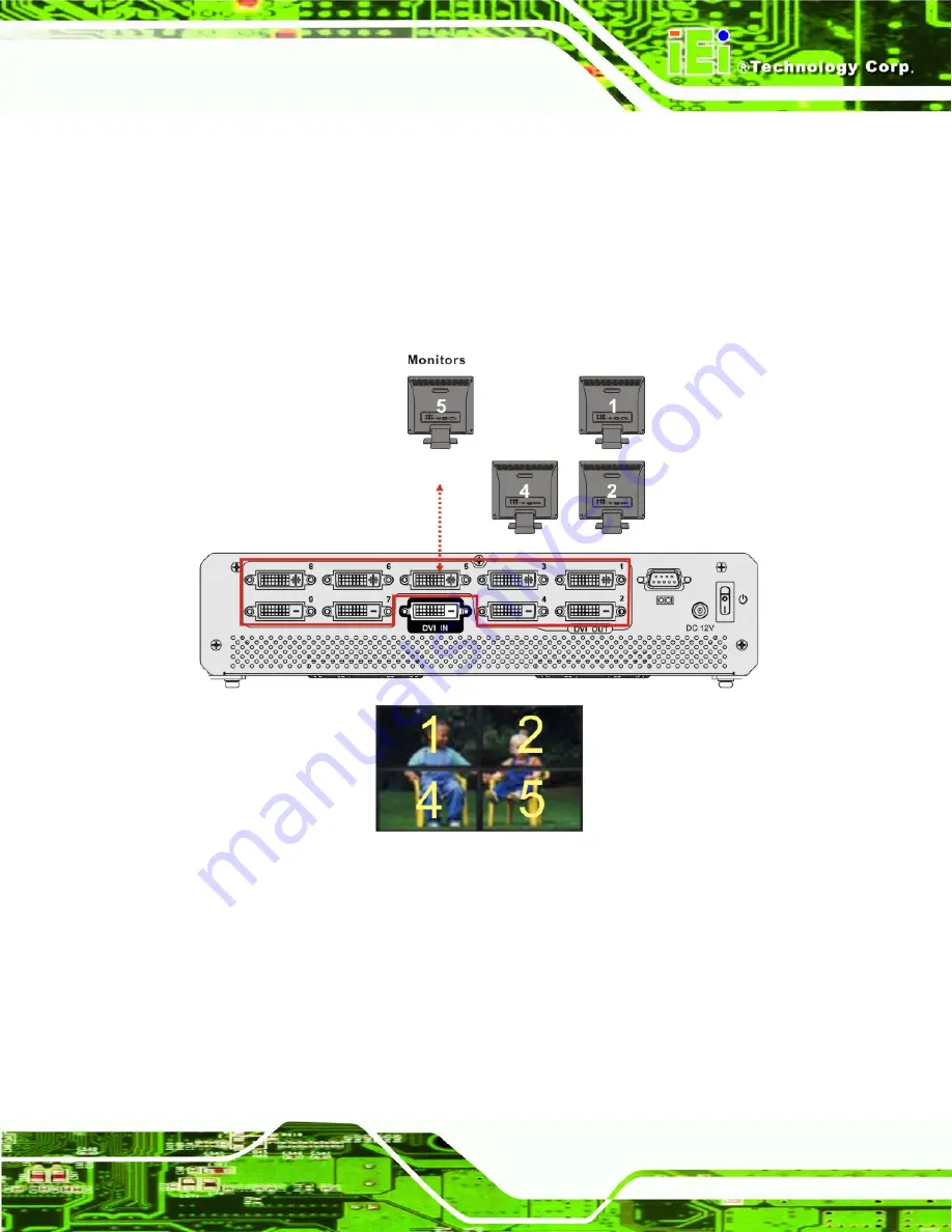
The VWBOX-E133 supports 4-panel, 6-panel, 9-panel, 36-panel (requires five video 

boxes) and 81-panel setups (requires ten video boxes). 

3.1.1 Four (2x2) Panel Overview 

The implementation of a 4-panel (2x2) array is shown in 

298H

Figure 3-4

 below. 

Figure 3-1: Four (2x2) Panel Setup 

Summary of Contents for VWBOX-E133

Page 1: ...VWBOX E133 Video Wall Controller Page i IEI Technology Corp User Manual VWBOX E133 MODEL Video Wall Controller 3x3 LCD Panel Array Scalable Rev 1 00 9 July 2009...

Page 2: ...VWBOX E133 Video Wall Controller Page ii Revision Date Version Changes 9 July 2009 1 00 Initial release...

Page 3: ...amages arising out of the use or inability to use the product or documentation even if advised of the possibility of such damages This document contains proprietary information protected by copyright...

Page 4: ...13H2 4 OPTIONAL ITEMS 166H19 14H3 INSTALLATION 167H20 15H3 1 INSTALLATION OVERVIEW 168H21 16H3 1 1 Four 2x2 Panel Overview 169H21 17H3 1 2 Six 2x3 Panel Overview 170H22 18H3 1 3 Six 3x2 Panel Overview...

Page 5: ...ge 193H38 41H4 2 2 3 Setting Page 194H40 42H4 2 2 4 About Page 195H42 43H4 2 3 Install Software 196H42 44H4 2 4 Troubleshooting 197H46 45H4 2 4 1 Windows 2000 Installation Failure 198H46 46H4 2 4 2 Vi...

Page 6: ...FORMAT 224H65 72HA 3 COMMAND REFERENCE 225H66 73HA 3 1 Get Display Status 226H67 74HA 3 2 Get Factory Defaults 227H68 75HA 3 3 Set Mask Control 228H69 76HA 3 4 Set Display Mode 229H70 77HA 3 5 Set Dis...

Page 7: ...VWBOX E133 Video Input 253H30 101HFigure 3 10 Serial Device Connector 254H31 102HFigure 3 11 Display Mode 255H33 103HFigure 4 1 smartOSD Interface Page 256H37 104HFigure 4 2 smartOSD Display Page 257H...

Page 8: ...re 4 16 Mask Formula 271H53 119HFigure 4 17 Display Menu 272H54 120HFigure 4 18 Information Screen 273H55 121HFigure 4 19 Input Select 274H56 122HFigure 4 20 Input Select 275H57 123HFigure 4 21 Input...

Page 9: ...130HTable 5 1 RS 232 Setup 283H65 131HTable 5 2 n Byte Data Output Format 284H65 132HTable 5 3 Get Display Status 285H67 133HTable 5 4 Get Factory Defaults 286H68 134HTable 5 5 Set Mask Control 287H6...

Page 10: ...VWBOX E133 Video Wall Controller Page 10 Chapter 1 1 Introduction...

Page 11: ...a single DVI input which is split over all the monitors in the array 1 2 Benefits The benefits of the VWBOX E133 include Accurate high definition image Silent operation Simple setup Cheap implementat...

Page 12: ...he VWBOX E133 1 4 1 Front Panel The front panel has the following buttons and indicators Power indicator LED Video output LEDs Video input LED OSD menu keypad Figure 1 2 VWBOX E133 Front Panel 1 4 2 R...

Page 13: ...e link Outputs Nine DVI D single link Dimensions W x D x H 295 mm x 190 mm x 65 mm 71 4mm with rubber feet Cooling Fan Input Resolution 800x600 1024x768 1152x864 1280x768 1280x960 1280x1024 1600x1200...

Page 14: ...VWBOX E133 Video Wall Controller Page 14 Specification Detail Safety and Emission CCC CE FCC Temperature 0 C 40 C Power Consumption 35 W Table 1 1 Technical Specifications...

Page 15: ...VWBOX E133 Video Wall Controller Page 15 1 6 Dimensions Height 65 mm 71 4mm with rubber feet Width 295 mm Depth 190 mm Figure 1 4 VWBOX E133 Dimensions...

Page 16: ...VWBOX E133 Video Wall Controller Page 16 Chapter 2 2 Unpacking List...

Page 17: ...i static wristband can help to prevent ESD from damaging the board Self grounding Before handling the board touch any grounded conducting material During the time the board is handled frequently touch...

Page 18: ...ler or vendor that sold the VWBOX E133 from or contact an IEI sales representative directly To contact an IEI sales representative please send an email to 142Hsales iei com tw The VWBOX E133 is shippe...

Page 19: ...ge 19 No Description Image 1 User manual CD Table 2 1 Package List Contents 2 4 Optional Items The following optional items are available for the VWBOX E133 No Description Image 1 Single link DVI D ca...

Page 20: ...VWBOX E133 Video Wall Controller Page 20 Chapter 3 3 Installation...

Page 21: ...The VWBOX E133 supports 4 panel 6 panel 9 panel 36 panel requires five video boxes and 81 panel setups requires ten video boxes 3 1 1 Four 2x2 Panel Overview The implementation of a 4 panel 2x2 array...

Page 22: ...VWBOX E133 Video Wall Controller Page 22 3 1 2 Six 2x3 Panel Overview The implementation of a 6 panel 2x3 array is shown in 299HFigure 3 4 below Figure 3 2 Six 2x3 Panel Setup...

Page 23: ...VWBOX E133 Video Wall Controller Page 23 3 1 3 Six 3x2 Panel Overview The implementation of a 6 panel 3x2 array is shown in 300HFigure 3 4 below Figure 3 3 Six 3x2 Panel Setup...

Page 24: ...VWBOX E133 Video Wall Controller Page 24 3 1 4 Nine 3x3 Panel Overview The implementation of a 9 panel 3x3 array is shown in 301HFigure 3 4 below Figure 3 4 Nine Panel Setup...

Page 25: ...el array using one VWBOX E133 as the master device and nine VWBOX E122 controllers as slave devices is shown in 302HFigure 3 5 below Each VWBOX E122 slave controller connects to four display panels Re...

Page 26: ...ray using one VWBOX 133A as the master device and nine VWBOX E133 controllers as slave devices is shown in 303HFigure 3 5 below Each VWBOX E133 slave controller connects to nine display panels in a 3x...

Page 27: ...square array with two rows and two columns for a total of four monitors Recommended installation procedures are to Use all identical monitors Keep gaps between panels as small as possible for the bes...

Page 28: ...04HFigure 3 8 DVI D input cable from the video source or computer to the VWBOX E133 DVI D output cables from the VWBOX E133 to the LCD panels or other slave video box controllers Make sure the cables...

Page 29: ...o source to the VWBOX E133 If the video source is a computer with the smartOSD software installed that computer can be used to adjust the monitor settings without using the OSD The video source connec...

Page 30: ...S 232 cable connects to a computer that has the smartOSD software installed This enables the computer to control the screen setup If the video source is from a PC the image screen setup can be control...

Page 31: ...then connect the PSU to the VWBOX E133 The figure below shows the typical setup There is no power switch and the VWBOX E133 turns on as soon as it is connected to the PSU 3 6 Input and Output Resolut...

Page 32: ...limits 3 6 3 Output Resolution The output resolution should be set as high as possible and meet the following criteria for best results Matches video input and LCD panel resolution ratios Is the maxi...

Page 33: ...VWBOX E133 Video Wall Controller Page 33 Figure 3 11 Display Mode...

Page 34: ...VWBOX E133 Video Wall Controller Page 34 Chapter 4 4 OSD Functions...

Page 35: ...d making setup time up to five times faster then individually setting up each video controller Use either the smartOSD 310H4 2 2 2 or OSD menu 311H4 3 4 1 to set the mask value 4 2 smartOSD IEI smartO...

Page 36: ...the smartOSD menu structure 312HTable 4 1 Menu Options Interface Interface Selection Display Display Resolution Display Mode Mask Setting Setting Digital I O Test for VWBOX E122 only Input Source Pow...

Page 37: ...lects the data communication method between the computer and the VWBOX E133 If the computer also provides the video input then communication can be done over the DVI cable Serial ports can also be use...

Page 38: ...igure 4 2 smartOSD Display Page Display Resolution The Display Resolution setting shows the resolution of the video image output Display output setting options are shown below 1024 x 768 60 MHz 1360 x...

Page 39: ...is split across a nine panel array in a 3 x 3 setup Mask Mode Mask mode toggles the masking function Off The video box doesn t compensate for gaps between LCD panels On DEFAULT The video box compensat...

Page 40: ...O settings are for the VWBOX E122 only Input Source The input video source is automatically selected by the VWBOX E133 DVI Input video source is DVI Power The power option turns the VWBOX E133 on and...

Page 41: ...available for resetting the values Factory Default Resets the video box to the factory defaults OSD Mode Two sets of options are available The lock unlock option sets whether the front panel OSD butt...

Page 42: ...gure 4 4 smartOSD About Page 4 2 3 Install Software To install the software please follow the steps below Step 1 Follow the instructions from the interactive installer to install the IEI smartOSD on t...

Page 43: ...VWBOX E133 Video Wall Controller Page 43 Figure 4 5 smartOSD Setup Wizard Step 4 Click Next to continue Step 5 The screen below appears Figure 4 6 smartOSD Select Installation Folder...

Page 44: ...m the screen shown above Step 7 Click Next to continue Step 8 The screen shown below appears Figure 4 7 smartOSD Confirm Installation Step 9 Confirm the installation by clicking Next in the screen abo...

Page 45: ...Video Wall Controller Page 45 Figure 4 8 smartOSD Installing Step 11 When the installation is complete the screen below appears Figure 4 9 smartOSD Installation Complete Step 12 Click Close in the sc...

Page 46: ...ow Step 14 To access the smartOSD click the smartOSD wizard logo on the desktop S t e p 0 4 2 4 Troubleshooting For troubleshooting please see the steps below 4 2 4 1 Windows 2000 Installation Failure...

Page 47: ...Page 47 4 2 4 2 Vista Installation Failure Installation fails under Vista while showing following image Figure 4 11 Windows Vista Error Solution Install smartOSD exe as the administrator authority Fig...

Page 48: ...rns the video box on and off Menu Enter Enters the OSD selects items and sets the new values entered Left Moves the selection left Right Moves the selection right Up Moves the selection up Down Moves...

Page 49: ...le below shows the OSD menu structure Menu Options Submenu Options Display Output Display Mode Mask Horizontal Mask Vertical Mask Mask On Off Setting Factory Information Input DVI Component Miscellane...

Page 50: ...Figure 4 14 Display Menu Display Resolution The Display Resolution setting shows the resolution of the video image output Display output setting options are shown below 1024 x 768 60 MHz 1360 x 768 60...

Page 51: ...e video input is tiled over all the panels 2 x 3 The video input is split across a six panel array in a 2 x 3 setup 3 x 2 The video input is split across a six panel array in a 3 x 2 setup 3 x 3 The v...

Page 52: ...settings compensate for the gaps between monitors in the video wall array The mask control options are shown and described below Figure 4 15 Mask Control Horizontal Mask Set the horizontal mask accor...

Page 53: ...age 53 Figure 4 16 Mask Formula Mask Control The mask control option turns the mask control on and off Off DEFAULT The video box doesn t compensate for the gap between monitors On The video box compen...

Page 54: ...nu Factory Reset Factory reset returns all the settings to the factory default settings Information Shows video box version information The information details are shown in 319H4 3 5 1 Input Select In...

Page 55: ...array 4 3 5 1 Information The information screen in 322HFigure 4 18 shows some basic information about the video box and the monitor The details are described below Figure 4 18 Information Screen Mode...

Page 56: ...r Page 56 4 3 5 2 Input Select The input select screen in 323HFigure 4 19 shows the input options Figure 4 19 Input Select The video box automatically selects the correct input source setting The foll...

Page 57: ...aneous The miscellaneous menu 324HFigure 4 20 allows the option to go to the OSD setup menu Figure 4 20 Input Select OSD Configuration OSD configuration adjusts the display settings for the OSD displa...

Page 58: ...5 3 1 OSD Configuration The OSD configuration menu 326HFigure 4 21 adjusts the rotation of the OSD and how long it displays for Figure 4 21 Input Select OSD Timer The OSD Timer sets how long the OSD...

Page 59: ...1H327HFigure 4 22 shows the remote control and its function keys Figure 4 22 Remote Control Power Turns the video box on and off Menu Enter Enters the OSD selects items and sets the new values entered...

Page 60: ...VWBOX E133 Video Wall Controller Page 60 Chapter 5 5 Troubleshooting and Maintenance...

Page 61: ...ally susceptible to ESD It is therefore critical that whenever the VWBOX E133 or any other electrical component is handled the following anti static precautions are strictly adhered to Wear an anti st...

Page 62: ...followed to ensure the embedded system can continue to operate normally 5 3 Troubleshooting This section provides some simple troubleshooting suggestions 5 3 1 No Image on One Monitor If there is no i...

Page 63: ...Any Monitor If no image displays on any monitors repeat the steps in Section 329H5 3 1 for all the monitors in the array then try the following additional steps 5 3 3 1 Check Video Box Power Make sure...

Page 64: ...VWBOX E133 Video Wall Controller Page 64 Appendix A A RS 232 Setup...

Page 65: ...8 Stop bit 1 Flow control None Table 5 1 RS 232 Setup A 2 Packet Format The generalized format of a single data packet on the RS 232 communications port is shown in 331HTable 5 2 The specific setup de...

Page 66: ...RS 232 communications port The following commands are detailed 144HGet display status 332H67 145HGet factory defaults 333H68 146HSet mask control 334H69 147HSet display mode 335H70 148HSet display re...

Page 67: ...68 2 1280 x 1024 3 1400 x 1500 4 1680 x 1050 5 1600 x 1200 6 1920 x 1200 7 1366 x 768 8 1920 x 1080 4 Output display mode 0 1 x 1 mode 1 2 x 2 mode 2 2 x 3 mode 3 3 x 2 mode 4 3 x 3 mode 5 Mask contro...

Page 68: ...roller Page 68 A 3 2 Get Factory Defaults Byte Value 1 0x09 2 0x04 3 Input source 2 DVI 4 Power 0 Power off 1 Power on 5 OSD lock unlock 0 OSD unlock 1 OSD lock 9 Checksum 0xff 1 2 3 4 5 6 7 8 9 Table...

Page 69: ...Mask Control Byte Value 1 0x07 2 0x18 3 Display mode 0 1 x 1 mode 1 2 x 2 mode 2 2 x 3 mode 3 3 x 2 mode 4 3 x 3 mode 4 Horizontal mask percent 0 10 5 Vertical mask percent 0 10 6 Mask control 0 Off...

Page 70: ...ode 2 2 x 3 mode 3 3 x 2 mode 4 3 x 3 mode 4 0xff 1 2 3 Table 5 6 Set Display Mode A 3 5 Set Display Resolution Byte Value 1 0x04 2 0x1A 3 Output resolution 0 1024 x 768 1 1360 x 768 2 1280 x 1024 3 1...

Page 71: ...1 A 3 6 Set Input Source Byte Value 1 0x04 2 0x1B 3 Input source 2 DVI 4 0xff 1 2 3 Table 5 8 Set Input Source A 3 7 Set Power Control Byte Value 1 0x04 2 0x1C 3 Power control 0 power off 1 power on 4...

Page 72: ...Default Byte Value 1 0x04 2 0x01 3 Defaults 0 auto adjust 1 factory defaults 4 0xff 1 2 3 Table 5 10 Set to Default A 3 9 Set OSD Mode Byte Value 1 0x04 2 0x02 3 OSD Mode 0 OSD unlock 1 OSD lock 4 OSD...

Page 73: ...VWBOX E133 Video Wall Controller Page 73 Appendix B B DDC2BI Setup...

Page 74: ...rite settings to the VWBOX E133 Code VCP Code Names Type Description B0h Display Resolution Read Write 0 1024x768 1 1360x768 2 128x1024 3 1400x1050 4 1680x1050 5 1600x1200 6 1920x1200 7 1366 x 768 8 1...

Page 75: ...Names Type Description 60h Video Source Read Write 2 DVI 14h Factory reset Write only 1 reset to factory defaults FCh OSD Mode Read Write 0 OSD Unlock 1 OSD Lock 2 OSD Normal F8h Get Model ID Read onl...

Page 76: ...VWBOX E133 Video Wall Controller Page 76 Appendix C C Terminology...

Page 77: ...es or TTL devices Data can be read or written to the selected address to enable the DIO functions DVI The Digital Video Interface standard allows analog and digital video transmission GPIO General pur...

Page 78: ...VWBOX E133 Video Wall Controller Page 78 Appendix D D Hazardous Materials Disclosure...

Page 79: ...the presences of small quantities of certain materials in the product and is applicable to China RoHS only A label will be placed on each product to indicate the estimated Environmentally Friendly Us...

Page 80: ...ircuit Board X O O O O X Metal Fasteners X O O O O O Cable Assembly X O O O O X Fan Assembly X O O O O X Power Supply Assemblies X O O O O X Battery O O O O O O O This toxic or hazardous substance is...

Page 81: ...BOX E133 Video Wall Controller Page 81 RoHS RoHS Pb Hg Cd CR VI PBB PBDE X O O O O X X O O O O X X O O O O X X O O O O O X O O O O X X O O O O X X O O O O X O O O O O O O SJ T11363 2006 X SJ T11363 20...

Reviews: