VWBOX-E133 Video Wall Controller
Page 30
Step 1:
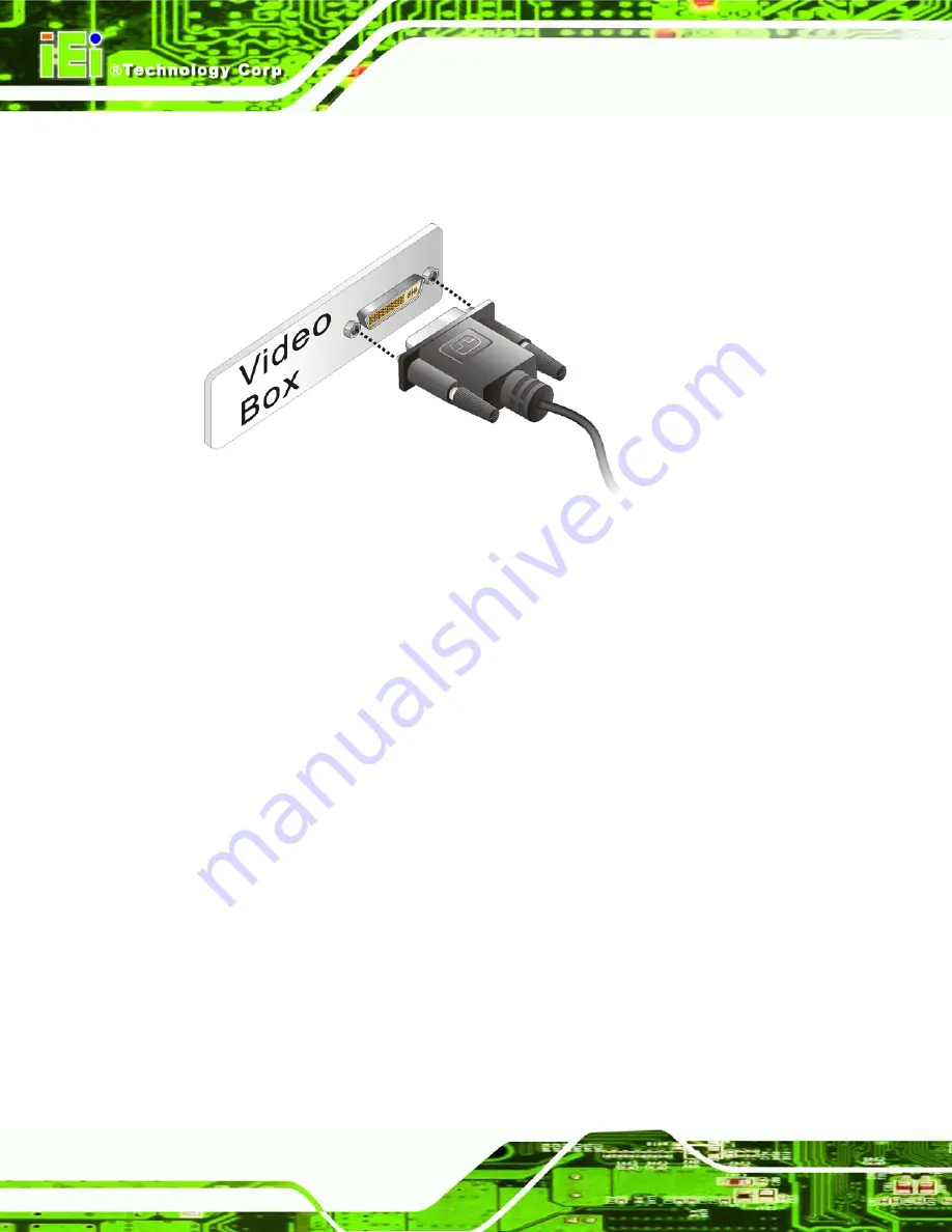
Attach the DVI video cable to the DVI output of the video source.
Step 2:
Attach the DVI video cable to the DVI input on the VWBOX-E133.
Step 0:
Figure 3-9: VWBOX-E133 Video Input
3.5.2 Connect the RS-232 Cable to the VWBOX-E133 (Optional)
The VWBOX-E133 has a male DB-9 connector on the rear panel. The RS-232 cable
connects to a computer that has the smartOSD software installed. This enables the
computer to control the screen setup. If the video source is from a PC the image screen
setup can be controlled through the DVI cable. Follow the steps below to connect a serial
device to the VWBOX-E133.
Step 1:
Locate the DB-9 connector
. The location of the DB-9 connector is shown in
Chapter 3
.
Step 2:
Insert the serial connector
.
Insert the DB-9 connector of a serial device into
the DB-9 connector on the external peripheral interface. See
306H
Figure 3-10
.
Summary of Contents for VWBOX-E133
Page 10: ...VWBOX E133 Video Wall Controller Page 10 Chapter 1 1 Introduction...
Page 16: ...VWBOX E133 Video Wall Controller Page 16 Chapter 2 2 Unpacking List...
Page 20: ...VWBOX E133 Video Wall Controller Page 20 Chapter 3 3 Installation...
Page 33: ...VWBOX E133 Video Wall Controller Page 33 Figure 3 11 Display Mode...
Page 34: ...VWBOX E133 Video Wall Controller Page 34 Chapter 4 4 OSD Functions...
Page 60: ...VWBOX E133 Video Wall Controller Page 60 Chapter 5 5 Troubleshooting and Maintenance...
Page 64: ...VWBOX E133 Video Wall Controller Page 64 Appendix A A RS 232 Setup...
Page 73: ...VWBOX E133 Video Wall Controller Page 73 Appendix B B DDC2BI Setup...
Page 76: ...VWBOX E133 Video Wall Controller Page 76 Appendix C C Terminology...
Page 78: ...VWBOX E133 Video Wall Controller Page 78 Appendix D D Hazardous Materials Disclosure...


