NANO-HM651 EPIC SBC
Page 21
Reset
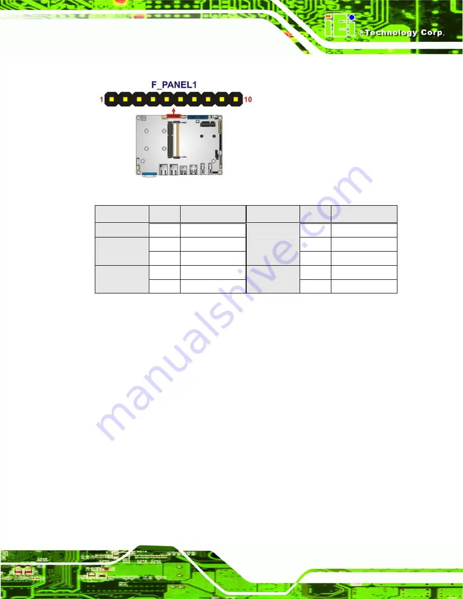
Figure 3-8: Front Panel Connector Location
FUNCTION
PIN
DESCRIPTION
FUNCTION
PIN
DESCRIPTION
1 N/A
6
2
7
Power Button
3 PWR_BTN-
Power LED
8 PWR_LED-
4
9 RESET+
HDD LED
5 HDD_LED-
Reset
10 RESET-
Table 3-9: Front Panel Connector Pinouts
3.2.8 LVDS Backlight Inverter Connector
CN Label:
INVERTER1
CN Type:
5-pin wafer (1x5)
CN Location:
See
Figure 3-9
CN Pinouts:
See
Table 3-10
The backlight inverter connector provides power to an LCD panel.
Summary of Contents for NANO-HM651
Page 15: ...NANO HM651 EPIC SBC Page 1 Chapter 1 1 Introduction ...
Page 22: ...NANO HM651 EPIC SBC Page 8 Chapter 2 2 Unpacking ...
Page 26: ...NANO HM651 EPIC SBC Page 12 Chapter 3 3 Connectors ...
Page 51: ...NANO HM651 EPIC SBC Page 37 Chapter 4 4 Installation ...
Page 76: ...NANO HM651 EPIC SBC Page 62 Chapter 5 5 BIOS Screens ...
Page 107: ...NANO HM651 EPIC SBC Page 93 Appendix A A BIOS Options ...
Page 110: ...NANO HM651 EPIC SBC Page 96 Appendix B B One Key Recovery ...
Page 118: ...NANO HM651 EPIC SBC Page 104 Figure B 5 Partition Creation Commands ...
Page 152: ...NANO HM651 EPIC SBC Page 138 Appendix C C Terminology ...
Page 156: ...NANO HM651 EPIC SBC Page 142 Appendix D D Digital I O Interface ...
Page 159: ...NANO HM651 EPIC SBC Page 145 Appendix E E Watchdog Timer ...
Page 162: ...NANO HM651 EPIC SBC Page 148 Appendix F F Hazardous Materials Disclosure ...


