POC-17i/19i Series
Page 33
Step 3:
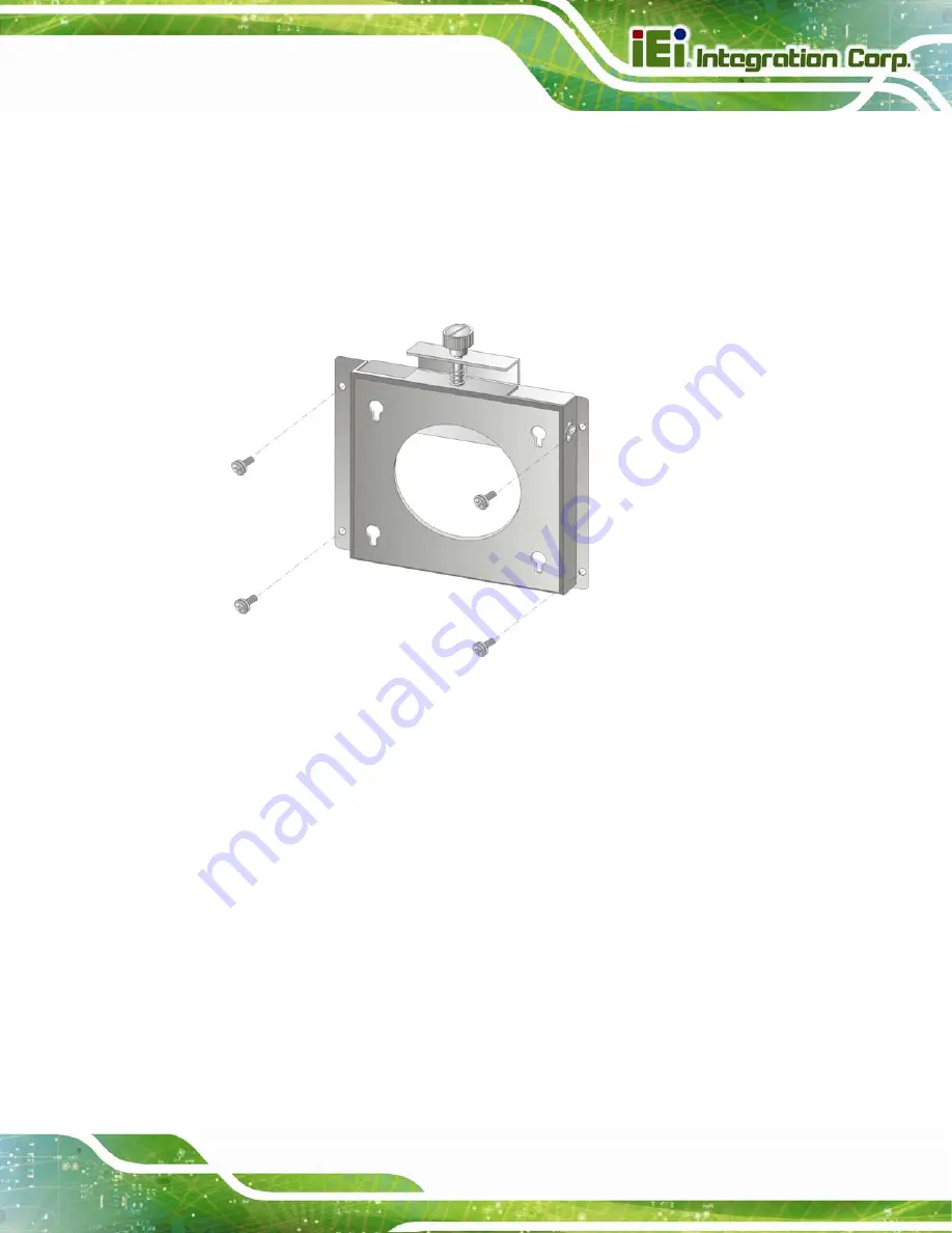
Drill four pilot holes at the marked locations on the wall for the bracket retention
screws.
Step 4:
Align the wall-mounting bracket screw holes with the pilot holes.
Step 5:
Secure the mounting-bracket to the wall by inserting the retention screws into
the four pilot holes and tightening them (
).
Figure 3-13: Wall-mounting Bracket
Step 6:
Insert the four monitor mounting screws provided in the wall mounting kit into the
four screw holes on the real panel of the flat panel PC and tighten until the screw
shank is secured against the rear panel (
Step 7:
Align the mounting screws on the monitor rear panel with the mounting holes on
the bracket.
Step 8:
Carefully insert the screws through the holes and gently pull the monitor
downwards until the monitor rests securely in the slotted holes (
).
Ensure that all four of the mounting screws fit snuggly into their respective
slotted holes.
Summary of Contents for POC-17i
Page 15: ...POC 17i 19i Series Page 1 Chapter 1 1 Introduction...
Page 25: ...POC 17i 19i Series Page 11 Chapter 2 2 Unpacking...
Page 28: ...POC 17i 19i Series Page 14 1 Touch pen 1 User manual CD and driver CD...
Page 29: ...POC 17i 19i Series Page 15 Chapter 3 3 Installation...
Page 56: ...POC 17i 19i Series Page 42 Chapter 4 4 System Maintenance...
Page 63: ...POC 17i 19i Series Page 49 Chapter 5 5 BIOS Setup...
Page 89: ...POC 17i 19i Series Page 75 Chapter 6 6 Software Drivers...
Page 113: ...POC 17i 19i Series Page 99 Figure 6 39 Reboot the Computer...
Page 114: ...POC 17i 19i Series Page 100 Appendix A A Safety Precautions...
Page 121: ...POC 17i 19i Series Page 107 Appendix B B BIOS Options...
Page 124: ...POC 17i 19i Series Page 110 Appendix C C Watchdog Timer...
Page 127: ...POC 17i 19i Series Page 113 Appendix D D Hazardous Materials Disclosure...


