20030516
User’s Manual
15
STAR FINGER007
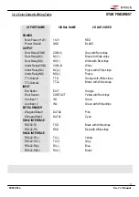
- Connect (+) wire of DC 12V power to +12V(Red wire) terminal.
- Connect GND(-) wire of DC 12V power to GND(Black wire) terminal.
5.4.2 INPUT CONNECTIONS
Exit Button Connection (EXIT)
- Connect one wire from an Exit Button to EXIT(Orange wire).
- Connect the other wire from the Exit Button to the GND(Black wire).
Door Contact Sensor Connection (CONTACT)
- Connect one wire from a Door Contact Sensor to CONTACT(Yellow with Red stripe).
- Connect the other wire from the Door Contact Sensor to GND(Black wire).
Auxiliary Input Connection (Applied IN1, IN2)
- Connect one wire from an Auxiliary Input Device to one of the IN1(Green wire), IN2(Green with White
stripe).
- Connect the other wire from the Auxiliary Input Device to GND(Black wire).
Figure : INPUT DEVICES CONNECTION
5.4.3 OUTPUT CONNECTIONS
Door Lock (Power Fail Safe) Connection (Relay 1)
- Connect COM port of Relay 1 to + 12V.
- Connect NC port of Relay 1 to (+)wire of door lock device.
- Connect GND port to (-)wire of door lock devices.
Door Lock (Power Fail Secure) Connection (Relay 1)
- Connect COM port of Relay 1 to + 12V.
- Connect NO port of Relay 1 to (+)wire of door lock device
- Connect GND port to (-)wire of door lock devices
Alarm Device Connection (Relay 2)
- Connect COM port of Relay 2 to + 12V.


