background image


HOWTO2


How to check if the Card Holder (ID) is properly registered.


(Procedure Based on FINGER007)


If the ‘Unregistered ID’ error occurs, it is sometimes because the ID is not registered properly in 

the device. You can confirm the list of registered IDs in the following way. If the problematic ID 

proves  to  be  unregistered,  you’ll  have  to  re-register  it  to  the  device.  To  find  out  about  how  to 

register an ID, refer to HELP3.   
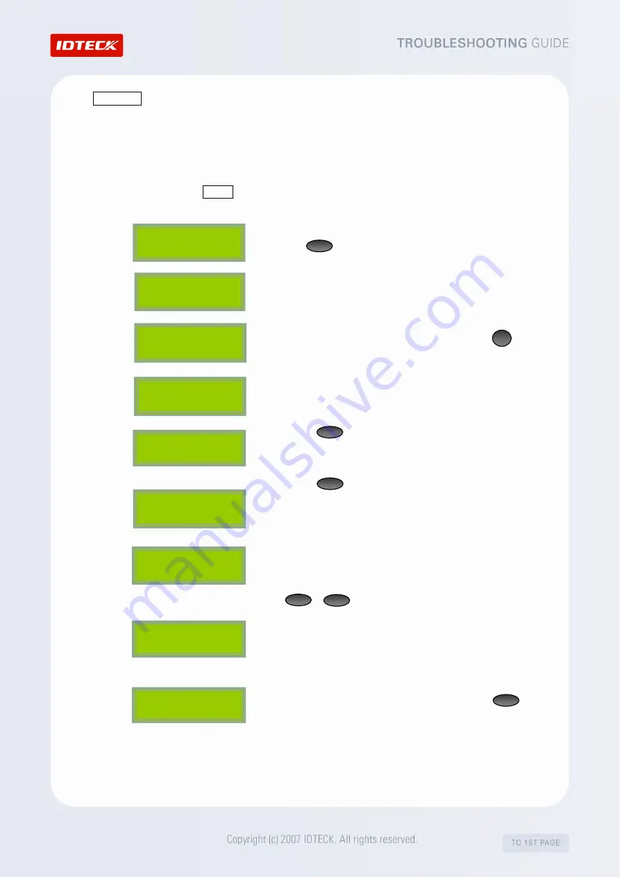
 

1. 

From the stand-by screen, enter the 8-digit master and press 

the                button using the keypad. (The default password is 

“00000000”) 


2. 

After  the  “Master  Password”  screen  is  displayed,  enter  the 

Master Password. (The default password is “3141”) 


3. 

The “Mode Selection” screen appears. Then, press             

to move to the F3 SETUP MENU. 


4. 

The “ID REGISTRATION” screen appears.   


5. 

Press                  twice, then the ‘ID LIST’ screen will appear.   


6. 

Press                ,  then  you  can  check  the  list  of  the  IDs 

registered  in  the  device.  If  there’s  no  ID  registered,  the 

‘MEMORY EMPTY’ appears.   


7. 

If  there  is  more  than  one  ID  registered,  information  such  as 

the ID number, password, assigned Time Schedule, assigned 

reader  number,  use  of  fingerprint  will  be  displayed.  Press                       

_          or              to see if the ID you’re looking for is registered.   


8. 

The “ID list TOP” and “ID list BOTTOM” messages mean that 

the  ID  you’re  looking  at  is  at  the  top  or  at  the  bottom  of  the 

list.   


9. 

After  you’re  done  with  the  ID  confirmation,  press                to 

quit the SETUP MENU. 


ID LIST 


MEMORY EMPTY 


ID list BOTTOM 

FINGER_007    [F1] 

MM/DD   hh:mm:ss 

XXXXXXXX 

XXXX  XX  XX  X 

  4

ENT

ESC

MODE SELECTION 

RF ONLY 

FINGER_007    [F1] 

MM/DD   hh:mm:ss 

Master   Password 

[ _ _ _ _ ] 

ENT

F3 

ID REGISTRATION 


Summary of Contents for FINGER007 Series

Page 1: ......

Page 2: ... discharge b During installation you have to connect the Battery Jumper as shown in Figure 2 so that the Controller can retain data in the event of power failure Figure 1 Battery Jumper location Figure 2 2 Initialization If an LCD module is connected to the iTDC a Apply DC power to the Controller and press the two INT Switches simultaneously Figure 3 b The LCD will display Initialized OK Turn OFF ...

Page 3: ...hen power off the Controller and return the DIP SW 8 to the ON position Then power on the Controller again Figure7 2 FINGER006 007 Series 505 Series FACE006 007 Series 1 Battery Switch Setting Turn on the backup battery switch as shown below 2 Initialization Hard Initialization 1 Power off the product and connect the yellow and cyan wires of the product to the GND Turn on the power See the diagram...

Page 4: ...r the password The default password 3141 3 The Mode Selection or READER 1 MODE screen appears 4 Press or until the LCD displays SYS INITIALIZE When it does press 5 Press and the System Initializing message will appear The system is being initialized NOTE All stored data will be lost after initialization 6 After the initialization is completed the LCD displays the SYS INITIALIZE message 7 Use to qu...

Page 5: ...itted signal will stabilize 18 6us after the leading edge of a bit Since the data bit is captured in the middle of the bit which is approximately 52us after the leading edge of a bit The reflection stabilizing time 18 6us is much before the center of the bit therefore the termination resistors are not required However if you install the cable to maximum length the impedance of cable and network is...

Page 6: ...hen the voltage level of both ends of shield wire is not equal and this current flow will create noise and interfere to communications For the good grounding we recommend to connecting ONLY one end of shield wire of communication cable to grounding system If you find earth ground nearby then connect one end of shield wire to earth ground If you do not have earth ground nearby then find chassis gro...

Page 7: ...ter the Password PW Time Schedule TS Reader to be assigned RD and Use of Fingerprint FP Enter appropriate values For fingerprint registration enter 1 in the FP field 8 After the To Register FP Put your FP on message appears and the fingerprint sensor is lit place the finger you d like to register on the fingerprint sensor 9 If the Lift and Put FP message appears lift your finger up and wait until ...

Page 8: ...r ID is 00000000 For some models it is 0000000000 2 After the Master Password screen appears enter the Master Password The default password is 3141 3 The Mode Selection Reader Mode1 screen appears You ve now entered the SETUP MODE and you can check the internal data and setting values 4 After you re done with the confirmation press to quit the SETUP MENU MODE SELECTION RF ONLY FINGER_007 F1 MM DD ...

Page 9: ...hen press to move to the F3 SETUP MENU 4 The ID REGISTRATION screen appears 5 Press twice then the ID LIST screen will appear 6 Press then you can check the list of the IDs registered in the device If there s no ID registered the MEMORY EMPTY appears 7 If there is more than one ID registered information such as the ID number password assigned Time Schedule assigned reader number use of fingerprint...

Reviews: