※
LX505/LX505SR QUICK INSTALLATION GUIDE
8
5. CONNECTION
5.1 Power Connection
- Connect DC 12V (+) wire of Power Supply to Red wire of LX505/LX505R.
- Connect GND (-) wire of Power Supply to Black wire of LX505/LX505R.
5.2 Input Connection
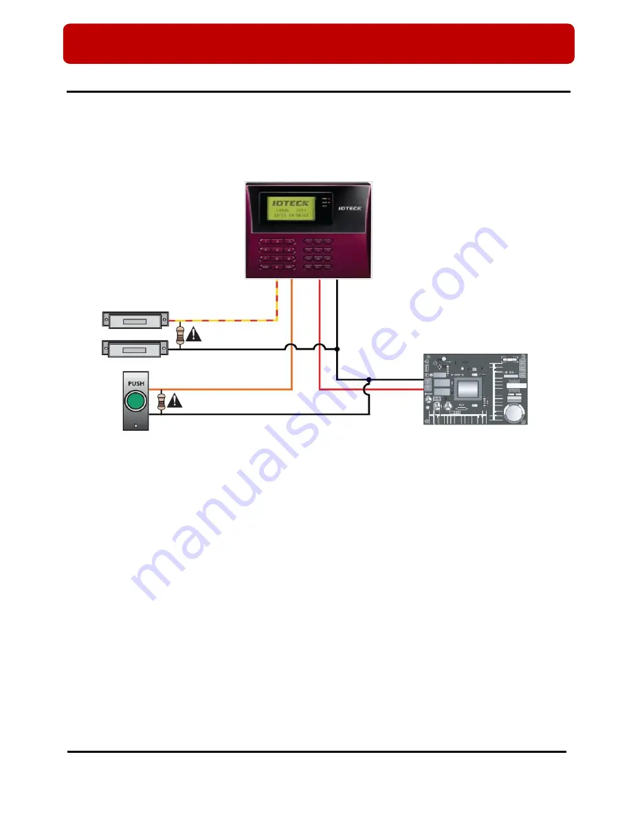
(Figure: Input Connection)
1. Connect the DC 12V(+) wire of the power supply to the red wire of LX505/LX505SR.
2. Connect the GND(-)wire of the power supply to the black wire of LX505/LX505SR.
Exit Button Connection
-
Connect one wire of Exit Button to Orange wire of LX505/LX505SR.
- Connect the other wire of Exit Button to GND of LX505/LX505SR.
Door Contact Sensor Connection
- Connect one wire of Door Contact Sensor to Yellow with Red stripe wire of LX505/LX505SR.
- Connect the other wire of Door Contact Sensor to GND of LX505/LX505SR.
Auxiliary Input
Device
Connection
(Applicable to Aux Input #1(Green wire), Aux Input #2(Green with white stripe wire))
- Connect one wire of Auxiliary Input Device to one of Aux Input #1 or Aux Input #2 of LX505/LX505SR.
- Connect the other wire from Auxiliary Input Device to GND of LX505/LX505SR.
Door Contact Sensor
Exit Button
Power Supply
Yellow with red stripes
GND
GND
Orange
GND (-)
DC 12V(+)
2.2K Resistor
2.2K Resistor
Red
Black


