background image


ZSSC4151Evaluation Kit Start-Up Guide       

© 2016 Integrated Device Technology, Inc. 

March 11, 2016 

2.4. 

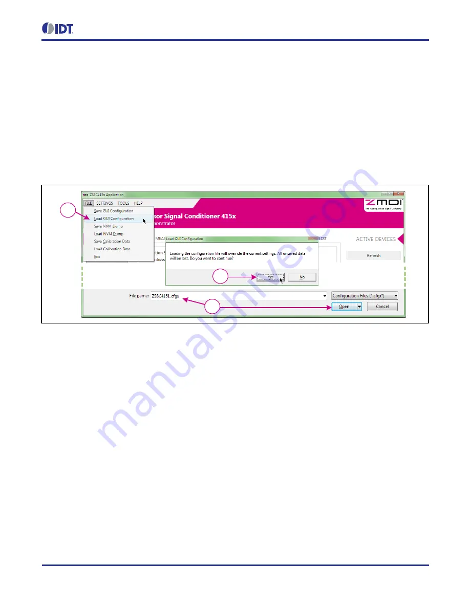
Creating and Loading the Default Configuration File 

1.  On the top menu, select 

FILE > Load GUI Configuration

 to load a configuration file (Figure 2.4). 

2.  A default configuration file, 

ZSSC4151.cfgx

, is provided with the software as shown in the “File name” 

field in Figure 2.4. If necessary, browse to the file location and click the “Open” button. 

3.  In the resulting “Load GUI Configuration” window, click the “Yes” button to accept overwriting the current 

configuration settings. 

Figure 2.4  Loading the GUI Configuration File  

1

3

2


Summary of Contents for ZSSC4151

Page 1: ...structions contained in this manual and in any other documentation provided to user or iii misuse abuse use under abnormal conditions or alteration by anyone other than IDT To the extent permitted by...

Page 2: ...the Hardware via I 2 C or OWI 5 Figure 2 4 Loading the GUI Configuration File 6 Figure 2 5 Load the NVM Data into GUI 7 Figure 2 6 Writing the Configuration into the ZSSC4151 NVM 7 Figure 2 7 Startin...

Page 3: ...handling of IC samples 2 Setting up Hardware and Software 2 1 Hardware Setup The Evaluation Kit hardware consists of the following three boards as shown in Figure 2 1 and includes samples of the ZSSC4...

Page 4: ...e first time that the SSC Communication Board is connected For this reason the PC should be connected to the Internet during the first USB connection so that the operating system can download a driver...

Page 5: ...ct I 2 C or OWI One Wire Interface from the drop down menu below Protocol see Figure 2 3 2 Click the Connect button On the Evaluation Board verify that the green LED power indicator turns on The ACTIV...

Page 6: ...load a configuration file Figure 2 4 2 A default configuration file ZSSC4151 cfgx is provided with the software as shown in the File name field in Figure 2 4 If necessary browse to the file location a...

Page 7: ...provided with the software as shown in the File name field in Figure 2 5 Browse to the file location and click the Open button 3 In the resulting Load RAM Dump window click the Yes button to accept o...

Page 8: ...utton to begin acquiring and recording measurements see Figure 2 7 2 With the Pressure selected in the Measurements pulldown turn the red knob on the Sensor Replacement Board Figure 2 1 The Pressure G...

Page 9: ...asurand and temperature 3 1 Setting up the Calibration and Acquiring Data 1 Select the Calibration tab to display the Calibration window see Figure 3 1 2 Ensure that the Calibration Type Settings and...

Page 10: ...lick the Calculate button The coefficients for the calibration will be calibrated and updated in the calibration formula textbox at the bottom of the window HINT Scroll to the bottom of the textbox so...

Page 11: ...he GUI settings and NVM contents for this example can be saved to new configuration and NVM dump files Select FILE Save GUI Configuration from the top menu and save the configuration under a new name...

Page 12: ...to the suitability of IDT s products for any particular purpose an implied warranty of merchantability or non infringement of the intellectual property rights of others This document is presented onl...

Reviews: