Page 14 of 68
VL-HP
Service
& Operation Manual
U.S. TAX STAMPING
EQUIPMENT
Manufactured by United Silicone
an ITW company
3.2 Air
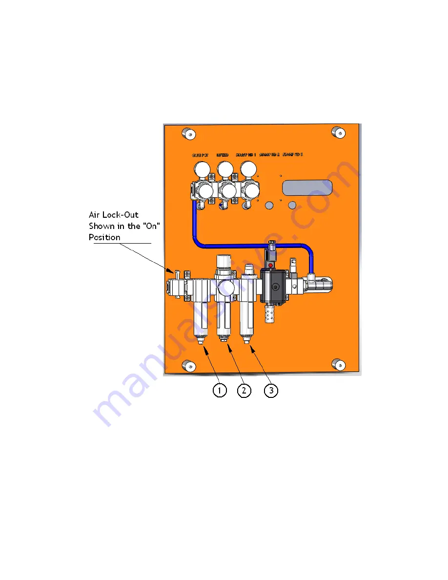
An air control valve is located on the pneumatic panel located on the back of the stamp machine,
near the electrical panel. For the stamp machine to operate, the air lockout must be pushed
upwards to the correct position. This valve is “Lock-Out, Tag-Out” compliant and a lock can be
applied with the valve in the “Off” position.
Figure 3.2 Air inlet panel
Prior to turning on the supply of compressed air to the stamping machine, it is important to check
for the presence of water in the water separator bowl (1), the filter bowl (2), and the coalescing
bowl (3). The VL-HP requires that the compressed air supplied to this stamping machine be
clean and dry. All air coming from an air compressor is “wet” as a result of being compressed
by the compressor. After the air compressor, the compressed air must be dried by passing
through an aftercooler and/or air dryer.
Types and advantages of different compressed air dryers
and other important information about air compressors are contained in Appendix A of this
manual “Supplying Compressed Air to your US Tax Stamping Equipment”.
Summary of Contents for VL-HP
Page 2: ......


