background image


Document   Version   1.0   

Last   revised   on   

2018-­‐10-­‐22   

Page   46   of   79   


Reference   Manual   for   uTrust   5501   F   Reader/Writer   Module   

6.3.3.1.


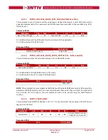
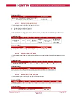
READER_SETMODE   

This   escape   command   sets   the   current   mode   of   the   reader.   Applications   may   call   this   function   to   set   
the   desired   mode.   Typically,   this   call   is   used   to   switch   between   the   ISO   7816,   EMV,   memory   card,   and   
NFC   test   mode   operations.   Upon   power   on,   the   reader   will   reset   to   the   default   ISO   7816   mode.   
   

Input:


The   first   byte   of   the   input   buffer   contains   the   escape   code   value   and   the   second   byte   contains   the   
value   for   the   desired   mode   of   operation.   The   output   buffer   field   shall   be   NULL.   
   

Byte0


Byte1


Escape   code   (0x01)    Mode      
   
   
The   following   table   defines   the   values   for   the   mode   parameter:   

Mode


Value


Remarks


ISO   7816   

0x00   

ISO   7816   mode   –   Applicable   for   both   contact   and   contactless   slots   

EMV   

0x01   

EMV   –   Applicable   only   for   contact   slot   and   ignored   by   contactless   
interface   

Synchronous    0x02   

Memory   card   mode   (synchronous)   –   Applicable   only   for   contact   slot   
and   ignored   by   contactless   interface      

NFC   Test   

0x04   

NFC   test   mode   –   Applicable   only   for   contactless   interface   


ISO   mode   uses   APDU   mode   of   data   transfer   and   is   used   for   normal   operation.   This   is   the   default   mode   
of   the   reader   on   power   up.   
   
EMV   mode   also   uses   APDU   mode   of   data   transfer   and   is   used   for   EMV   test   purposes.   This   mode   has   
more   stringent   checks   for   smartcard   detection   and   communication   as   per   EMV4.2   spec.   
   
Synchronous   mode   is   used   for   communicating   only   with   memory   cards.      
   
NFC    test    mode    is    used    to    ignore    deactivate-­‐activate    sequence    during    SCardConnect.   
(PC_TO_RDR_ICCPOWERON   -­‐   0x62,   and   PC_TO_RDR_ICCPOWEROFF   –   0x63).   


Output:   


Output   buffer


NULL   


Summary of Contents for uTrust 5501F

Page 1: ...Reference Manual for uTrust 5501F Multi Technology Secure Smart Card Reader Writer Module For Part 905567 Document Version 1 0 Last Revised On 2018 10 23...

Page 2: ...th information about the hardware and software features of the uTrust 5501 F Multi Technology Secure Smart Card Reader Writer Module Audience This document is intended for system integrators and softw...

Page 3: ...5501 F ordering information 11 3 4 uTrust 5501 F customization options 12 3 5 Contactless communication principles and uTrust 5501 F usage recommendations 12 3 5 1 Power supply 12 3 5 2 Data exchange...

Page 4: ...2 12 PAPDU_ISO14443_PART4_PART3_SWITCH TCL Mifare Switch 36 6 2 13 PAPDU_FELICA_REQC 36 6 2 14 PAPDU_FELICA_REQ_SERVICE 37 6 2 15 PAPDU_FELICA_REQ_RESPONSE 37 6 2 16 PAPDU_FELICA_READ_BLK 37 6 2 17 PA...

Page 5: ...COLLISION_DETECTED 64 6 3 4 15 CNTLESS_FELICA_PASS_THRU 64 6 3 4 16 CNTLESS_CONTROL_KBD_EMULATION 64 6 3 4 17 CNTLESS_LF_COMMAND_SET 65 6 3 5 Specific for Contact Interface 65 6 3 5 1 CONTACT_GET_SET_...

Page 6: ...nt please provide your feedback to support identiv com 1 2 Licenses If the document contains source code examples they are provided for illustrative purposes only and are subject to the following rest...

Page 7: ...pported commands available for developers using uTrust 5501 F in their applications 2 2 Target Audience This document describes the technical implementation of uTrust 5501 F The manual targets softwar...

Page 8: ...ight emitting diode MIFARE The ISO14443 Type A with extensions for security NXP NA Not applicable NAD Node address Nibble Group of 4 bits 1 digit of the hexadecimal representation of a byte Example 0x...

Page 9: ...IEC LF_MANUAL uTrust 55xx LF Reader Manual Identiv PC SC Interoperability specification for ICCs and personal computer systems v2 01 PC SC Workgroup PCSC3 Interoperability specification for ICCs and...

Page 10: ...nted by lower case b where followed by a numbering digit Bytes are represented by upper case B where followed by a numbering digit Example 163 decimal number is represented in hexadecimal as 0xA3 in b...

Page 11: ...rface uTrust 5501 F s optional Secure Access Module SAM slot provides enhanced application security via secure authentication mutual authentication key management and smart card cryptographic function...

Page 12: ...chip connected to an antenna User credentials can take several form factors Credit card sized smart card Key fob USB token NFC mobile device Communication between uTrust 5501 F and credentials uses m...

Page 13: ...als The presence of multiple user credentials in the field also interferes with communication When several user credentials are in the field of the reader load of the field increases which implies tha...

Page 14: ...with the application related to the token or card The application specific logic has to be implemented by software developers on the host 3 6 2 Applications Provided by Identiv Inc Identiv Inc does n...

Page 15: ...Document Version 1 0 Last revised on 2018 10 22 Page 15 of 79 Reference Manual for uTrust 5501 F Reader Writer Module...

Page 16: ...indication Buzzer A contact smart card interface An RF front end that handles the RF communication The controller embeds flash memory that contains the firmware developed by Identiv to handle all ISO...

Page 17: ...freely available for all supported operating systems Windows macOS X and Linux With current Windows versions starting with Windows Vista and macOS X this driver is already included in the basic insta...

Page 18: ...ut occurs and LED will turn OFF Reader powered contactless card IN but not powered ON ON OFF Contact card powered communication ON ON 500 msec ON 500 msec OFF Blinks ON and OFF for 500 milliseconds Co...

Page 19: ...ported ISO IEC 7816 smart cards class A B and C synchronous smart cards ISO 7816 compliant Yes CT API compliant Yes Number of slots Single smart card slot and single SAM slot Ejection mechanism Manual...

Page 20: ...The following utilities are available A tool for testing the resource manager A tool called PCSCDiag capable of providing basic information about the reader and a card through PC SC stack 5 3 Driver 5...

Page 21: ...gy like MIFARE Byte Value Designation Description 0 0x3B Initial header 1 0x8n T0 n indicates the number of historical bytes in following ATR 2 0x80 TD1 upper nibble 8 indicates no TA2 TB2 TC2 lower n...

Page 22: ...rical bytes in following ATR 2 0x80 TD1 upper nibble 8 indicates no TA2 TB2 TC2 lower nibble 0 means T 0 3 0x01 TD2 upper nibble 0 indicates no TA3 TB3 TC3 lower nibble 1 means T 1 4 3 n Historical by...

Page 23: ...D messages are supported for the contact interface when received through bulk out endpoint PC_to_RDR_IccPowerOn PC_to_RDR_IccPowerOff PC_to_RDR_GetSlotStatus PC_to_RDR_XfrBlock PC_to_RDR_GetParameters...

Page 24: ...ICC_PROTOCOL_NOT_SUPPORTED This error code is returned if the card is signalling to use a protocol other than T 0 or T 1 in its ATR 5 4 1 3 4 BAD_ATR_TS This error code is returned if the initial char...

Page 25: ...l supported technologies Command APDU CLA INS P1 P2 Lc Data In Le 0xFF 0xCA 0x00 0x00 XX Setting Le 0x00 can be used to request the full UID or PUPI is sent back e g for ISO 14443A single 4 bytes doub...

Page 26: ...e READER_SETMODE 0X01 escape command this pseudo APDU would be used Command APDU FF CC 00 00 02 01 01 to set to EMV mode Response APDU 90 00 Note 1 To send escape commands using this method the reader...

Page 27: ...d binary 0xFF 0xB0 Addr MSB Addr LSB xx P1 and P2 represent the block number of the block to be read starting with 0 for sector 0 block 0 continuing with 4 for sector 1 block 0 sector no x 4 block no...

Page 28: ...Le Update Binary 0xFF 0xD6 Addr MSB Addr LSB xx data For a description of P1 and P2 see PAPDU_MIFARE_READ_BINARY Lc must match the block size of the used card 16 bytes for MIFARE Classic 4 bytes for...

Page 29: ...ion else it is ignored Only one reader key 0x00 is supported by uTrust 5501 F Notes 1 Card keys can be loaded in both secure and non secure mode Card keys can only be loaded to the volatile memory of...

Page 30: ...padding FFFFFFFF FFFF0A0A 0A0A0A0A 0A0A0A0A AES128 Encrypted 10229E33 189403FD A9C14110 B1BB02B4 Load keys command FF82406010 10229E33 189403FD A9C14110 B1BB02B4 Load Keys Reader Secure If the defaul...

Page 31: ...thenticate 0xFF 0x86 0x00 0x00 0x05 data xx The data structure is defined as follows Byte Value Description B0 0x01 Version B1 Block Number MSB always 0x00 for MIFARE Classic cards B2 Block Number LSB...

Page 32: ...e content of a MIFARE UL APDU FF B1 00 01 10 SW12 9000 OK DataOut 04 6B 5D BA 09 F8 01 80 70 48 00 00 E1 10 06 00 00 01 02 03 1D 6E 6F 6B 69 61 2E 63 6F 6D 3A 62 74 01 00 11 67 9F 5F B6 04 06 80 30 30...

Page 33: ...o the small sectors of a MIFARE Classic and 0xF0 when writing to the large sectors of a MIFARE Classic 4K Lc must be 0x30 for MIFARE UL the data will be written from block 4 through the end of the mem...

Page 34: ...a data object if the card supports it Refer to section 3 2 2 1 10 of PCSC3 AMD1 for further details Command APDU Command CLA INS P1 P2 Lc Data Le Increment Decrement FF C2 00 03 xx BER TLV 00 The data...

Page 35: ...81 Data object XX not supported XX 67 00 Data object XX with unexpected length XX 6A 80 Data object XX with unexpected vale XX 64 00 Data Object XX execution error no response from IFD XX 64 01 Data...

Page 36: ...CL Mifare Switch This command switches the card state between TCL and MIFARE modes Command APDU Command CLA INS P1 P2 P3 Data Part 4 Part 3 Switch FF F8 P1 00 00 P1 0x00 switches from MIFARE mode to T...

Page 37: ...of service or areas n service version or area version list 2 n SW1 SW2 6 2 15 PAPDU_FELICA_REQ_RESPONSE This command issues a REQ RESPONSE as defined in JIS 9 6 1 When an NFC Forum tag type 3 receive...

Page 38: ...Ca Write Block 0xFF 0x48 Number of service Number of blocks 2 P1 P2 16 P2 Service code list block list block data Response APDU Data Status Word 8 bytes IDm Status Flag 1 Status Flag 2 SW1 SW2 6 2 18...

Page 39: ...PDU Data Status Word HR0 HR1 120 bytes Blocks 0 E SW1 SW2 6 2 21 PAPDU_NFC_TYPE1_TAG_READ This command issues a READ to read a single EEPROM memory byte within the static memory model area of blocks 0...

Page 40: ...y half that of the normal write command WRITE E Using this command EEPROM bits can only be set not reset Command APDU Command CLA INS P1 P2 P3 Data TYPE1 Tag WRITE No ERASE FF 58 00 Byte Addr 01 Data...

Page 41: ...Document Version 1 0 Last revised on 2018 10 22 Page 41 of 79 Reference Manual for uTrust 5501 F Reader Writer Module 128 bytes of data SW1 SW2...

Page 42: ...Block Addr 00 P2 block address Bit Numbers Description b7 b0 General block 0x00 0xFF Response APDU Data Status Word 8 bytes of data SW1 SW2 6 2 26 PAPDU_NFC_TYPE1_TAG_WRITE_E8 This command issues a WR...

Page 43: ...Command CLA INS P1 P2 P3 Data TYPE1 Tag WRITE and NO ERASE BLOCK FF 60 00 Block Addr 08 Data P2 block address Bit numbers Description b7 b0 General block 0x00 0xFF Response APDU Data Status Word 8 byt...

Page 44: ...be enabled by setting a REG_DWORD value named EscapeCommandEnable in the registry to a value of 1 For Windows 7 Windows 8 Windows 8 1 and Windows 10 the key to hold the value for uTrust 5501F contact...

Page 45: ...ed mode or to get specific information To put uTrust 5501 F back into its default mode it must be unplugged and re plugged The following escape commands are supported by uTrust 5501 F 6 3 3 Common for...

Page 46: ...ter Mode Value Remarks ISO 7816 0x00 ISO 7816 mode Applicable for both contact and contactless slots EMV 0x01 EMV Applicable only for contact slot and ignored by contactless interface Synchronous 0x02...

Page 47: ...yte value Mode Value Remarks ISO 0x00 ISO 7816 mode EMV 0x01 EMV mode Synchronous 0x02 Memory card mode synchronous NFC Test 0x04 NFC Test Mode 6 3 3 3 READER_GET_IFDTYPE This escape command is used t...

Page 48: ...Unicode serial number Input The first byte of the input buffer contains the escape code Byte0 Escape code 0x1E Output The firmware will return data as per below structure SCARD_READER_GETINFO_PARAMS_E...

Page 49: ...Document Version 1 0 Last revised on 2018 10 22 Page 49 of 79 Reference Manual for uTrust 5501 F Reader Writer Module 28 abySerialNumber Unicode serial number Reader serial number MSB first...

Page 50: ...ontrol by firmware FF Get state 0 LED control by firmware enabled 1 LED control by firmware disabled Output No response is returned for set state For get state 1 byte response is received Output buffe...

Page 51: ...9 READER _CONTROL_CONTACT_SLOT This escape command is supported through the READER_GENERIC_ESCAPE message This command can be used to disable the contact slot until it is re enabled through the same c...

Page 52: ...x93 CNTLESS_GET_TYPE 0x94 CNTLESS_SET_TYPE 0x95 CNTLESS_CONTROL_PPS 0x99 CNTLESS_RF_SWITCH 0x96 CNTLESS_SWITCH_RF_ON_OFF 0x9C CNTLESS_CONTROL_848 0x9D CNTLESS_GET_BAUDRATE 0x9E CNTLESS_CONTROL_RETRIES...

Page 53: ...tion reader to card b1 424kbps supported direction reader to card b2 848kbps supported direction reader to card b3 always 0 b4 212kbps supported direction card to reader b5 424kbps supported direction...

Page 54: ...in the second byte Byte0 Byte1 0x94 Empty or 0xFF The output buffer shall point to a BYTE buffer in case the extension specifier is not given and will contain the type value coded as Value Descriptio...

Page 55: ...ed on 2018 10 22 Page 55 of 79 Reference Manual for uTrust 5501 F Reader Writer Module 1 125 KHz FSK 1 125 KHz ASK 1 125 KHz PSK 1 125 KHz EM 42XX 1 125 KHz HiTag2 Byte 2 and Byte 3 will be 0x00 each...

Page 56: ...r will immediately stop polling for the card it will never detect that the card is removed The input buffer shall contain two or three bytes Byte0 Byte1 Byte3 Description Escape code 0x95 0x00 Type A...

Page 57: ...Document Version 1 0 Last revised on 2018 10 22 Page 57 of 79 Reference Manual for uTrust 5501 F Reader Writer Module Output Buffer NULL...

Page 58: ...us 0 PPS is enabled 1 PPS is disabled Output No response is returned for set state For get state 1 byte response is received Output Buffer NULL or current state 6 3 4 6 CNTLESS_RF_SWITCH This escape c...

Page 59: ...e reader No Output 0xFF Get current field state 0x00 RF is OFF when contact card is present in the reader 0x01 RF is ON when contact card is present in the reader After the RF is turned off to turn th...

Page 60: ...both directions 0x01 106 Kbps from PICC to PCD 212 Kbps from PCD to PICC 0x02 106 Kbps from PICC to PCD 424 Kbps from PCD to PICC 0x03 106 Kbps from PICC to PCD 848 Kbps from PCD to PICC 0x10 212 Kbp...

Page 61: ...state of retries 0x00 Retries are enabled 0x01 Retries are disabled Output No response is returned for set state For get state 1 byte response is received Output buffer NULL or current state 6 3 4 11...

Page 62: ...DR 8 supported if bit is set to 1 b3 shall be set to 0 1 is RFU b4 DS 2 supported if bit is set to 1 b5 DS 4 supported if bit is set to 1 b6 DS 8 supported if bit is set to 1 b7 1 if the same D is re...

Page 63: ...h 0x08 For FeliCa cards THEN EITHER B3 B12 PUPI UID bytes 0x00 byte padding used if length smaller than 10 B13 0x00 CID not supported 0x01 CID supported B14 0x00 NAD not supported 0x01 NAD supported B...

Page 64: ...llowed by a FeliCa command to be sent to the card At least 1 byte of command is required to be sent to the card Otherwise an error will be reported Byte0 Byte1 onwards Escape code 0xF3 FeliCa command...

Page 65: ...Interface ESCAPE COMMAND Escape code CONTACT_GET_SET_PWR_UP_SEQUENCE 0x04 CONTACT_EMV_LOOPBACK 0x05 CONTACT_EMV_SINGLEMODE 0x06 CONTACT_EMV_TIMERMODE 0x07 CONTACT_APDU_TRANSFER 0x08 CONTACT_DISABLE_PP...

Page 66: ...rating voltage the firmware will continue card communication at that voltage If power up fails in all the enabled operating voltages then the firmware will report an error Input The first byte of the...

Page 67: ...A voltage 5V 3V 1 8V order For retrieving current power up sequence 0xFF the output will be Byte0 Value Description 0x00 Starts with Class C voltage 1 8V 3V 5V order 0x01 Starts with Class A voltage...

Page 68: ...V loop back application as specified in the EMV Level 1 Testing Requirements document Input The input buffer contains the escape code value Byte0 Escape code 0x07 Output Output buffer NULL 6 3 5 5 CON...

Page 69: ...0F PPS control byte 1 DISABLES PPS 0 ENABLES PPS Output Output buffer NULL 6 3 5 7 CONTACT_EXCHANGE_RAW This escape command can be used to perform raw exchange of data with the card The user must ensu...

Page 70: ...Document Version 1 0 Last revised on 2018 10 22 Page 70 of 79 Reference Manual for uTrust 5501 F Reader Writer Module...

Page 71: ...byte of the input buffer contains the escape code the next byte contains the clock divisor value to set the clock frequency or 0xFF to get the clock frequency Byte0 Byte1 Value Description Escape code...

Page 72: ...l byte Byte0 Byte1 Value Description Escape code 0x88 0x00 Enable ATR validation 0x01 Disable ATR validation Output Output buffer NULL 6 3 5 10 CONTACT_GET_SET_MCARD_TIMEOUT This escape command is use...

Page 73: ...IT16 BIT15 BIT8 BIT7 BIT0 DataIn 80 00 DataOut 00 00 01 40 4 bytes 6 3 5 12 CONTACT_GET_SET_WAITTIME This Escape command is used to get set the Character Block Waiting Time for smartcards The wait tim...

Page 74: ...uffer contains the escape code followed by an 8 bit get set identifier an 8 bit guard time identifier and a 32 bit guard time value in ETU Byte0 Byte1 Byte2 Byte3 Byte4 Byte5 Byte6 Value Description V...

Page 75: ...nnex A Status Words Table SW1 SW2 Description 0x90 0x00 NO ERROR 0x63 0x00 NO INFORMATION GIVEN 0x65 0x81 MEMORY FAILURE 0x67 0x00 LENGTH INCORRECT 0x68 0x00 CLASS BYTE INCORRECT 0x6A 0x81 FUNCTION NO...

Page 76: ...EMV_LOOPBACK 0x05 define CONTACT_EMV_SINGLEMODE 0x06 define CONTACT_EMV_TIMERMODE 0x07 define CONTACT_APDU_TRANSFER 0x08 define CONTACT_CONTROL_PPS 0x0F define CONTACT_EXCHANGE_RAW 0x10 define CONTACT...

Page 77: ..._SUCCESS s ReaderName 0 printf Connecting to reader s n s ret SCardConnect ContextHandle s SCARD_SHARE_DIRECT SCARD_PROTOCOL_UNDEFINED CardHandle ActiveProtocol if ret SCARD_S_SUCCESS InByte 0x1E ret...

Page 78: ...derInfo bySerialNoLength i if strReaderInfo abySerialNumber i 0 printf c strReaderInfo abySerialNumber i else printf SCardControl failed 08X n ret else printf SCardConnect failed 08X n ret ret SCardRe...

Page 79: ...Document Version 1 0 Last revised on 2018 10 22 Page 79 of 79 Reference Manual for uTrust 5501 F Reader Writer Module 7 3 Annex C Mechanical drawings Product outline End of document...

Reviews: