background image

12: M

ODBUS

 ASCII/RTU C

OMMUNICATION

FC5A M

ICRO

S

MART

 U

SER

S

 M

ANUAL

  FC9Y-B1268

12-9

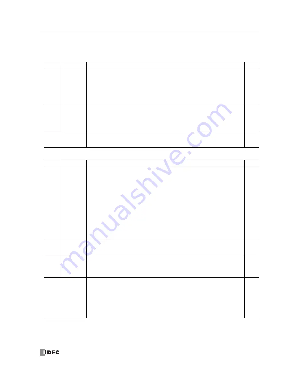
Device Addresses for Modbus Master

Special internal relays and special data registers are allocated to Modbus master communication as shown below.

Internal Relay and Special Internal Relay Device Addresses

Port 2

Ports 3 to 7

Description

R/W

M8005

Communication Error

When a communication error occurs, communication error special internal relay M8005 turns 
on for 1 scan time immediately after the error. Communication error occurs when communica-
tion failure has repeated more than the designated retry cycles or when the master station 
does not receive response within the designated receive timeout period. When a communica-
tion error occurs, the request is canceled and the next request is transmitted.
The completed request number and error code are stored to special data register D8053.

R

M8080

Modbus Communication Completion Relay

Immediately after a request communication has been completed, Modbus communication 
completion relay M8080 turns on for 1 scan time. Similarly, when an error occurs, M8080 turns 
on for 1 scan time. At the same time, the completed request number and error code are stored 
to special data register D8053.

R

Function Area Settings

Request Execution Device

When a request execution device is turned on, the corresponding request is executed. When 
communication is completed, the request execution device turns off automatically.

R/W

Data Register and Special Data Register Device Addresses

Port 2

Ports 3 to 7

Description

R/W

D8053
(Note)

Modbus Communication Error Code

When a Modbus communication is completed, the request number and error code are stored.

High-order 11 bits: Request No.

1 to 2040

Low-order 5 bits: Error code

00h: Normal completion
01h: Function error
02h: Access destination error (address out of range, device quantity out of range)
03h: Device quantity error, 1-bit write data error
11h: ASCII code error (ASCII mode only)
12h: Frame length error
13h: BCC error
14h: Slave number error
16h: Timeout error

R

D8054

Function 

Area Set-

tings

Modbus Communication Transmission Wait Time

When the MicroSmart sends communication, transmission wait time can be designated by 
storing a wait time value to D8054. Valid values are 1 through 5000 in milliseconds.

R/W

D8069-

D8099

Error Station Number and Error Code

When a communication error occurs in the Modbus communication, the slave number (high-
order byte) and error code (low-order byte) are stored to these data registers. Error codes are 
the same as D8053. When the CPU module is powered up, these data registers are cleared.

R

Function Area Settings

Error Status

When a communication error occurs in the Modbus communication, the slave number (high-
order byte) and error code (low-order byte) are stored to the Error Status data registers allo-
cated to each request. Error codes are the same as D8053. When the CPU module is powered 
up, these data registers are cleared.
When Use a single DR for all communication requests is selected, the Error Status data register 
is shared by all requests. The value in the data register is overwritten every time an error 
occurs.

R

Phone: 800.894.0412 - Fax: 888.723.4773 - Web: www.clrwtr.com - Email: [email protected]

Summary of Contents for MicroSmart pentra C5A-C10R2C

Page 1: ...FC5A SERIES FC9Y B1268 User s Manual Basic Volume Phone 800 894 0412 Fax 888 723 4773 Web www clrwtr com Email info clrwtr com ...

Page 2: ...m Counting Range 0 to 65535 16 bits 0 to 4 294 967 295 32 bits Multi stage Comparison Possible Comparison Action Comparison output Comparison output Interrupt program Frequency Measurement Possible Pulse Output Output Points 2 points maximum 3 points maximum Output Pulse Frequency 20 kHz maximum 100 kHz maximum Communication Baud Rate 19 200 bps maximum Data link 38 400 bps maximum 115 200 bps max...

Page 3: ...l result The environment for using the MicroSmart is Pollution degree 2 Use the MicroSmart in environments of pollution degree 2 according to IEC 60664 1 Prevent the MicroSmart from falling while moving or transporting the MicroSmart otherwise damage or malfunction of the MicroSmart will result Prevent metal fragments and pieces of wire from dropping inside the MicroSmart housing Put a cover on th...

Page 4: ...0 or higher 101 or higher 5 60 FC5A SIF2 Expansion RS232C Communi cation Module Compatibility Note 3 110 or higher 5 1 or higher 2 86 Advanced Vol 25 1 Modbus Master Upgrade Note 4 12 6 Modbus Slave Upgrade Note 4 110 or higher 110 or higher 12 14 32 bit Data Storage Setting 5 2 or higher 5 46 Forced I O 200 or higher 200 or higher 200 or higher 5 72 RUN LED Flashing Mode 5 49 Memory Cartridge Upl...

Page 5: ...on XCHG Advanced Vol 3 15 Increment Instruction INC Advanced Vol 5 13 Decrement Instruction DEC Advanced Vol 5 13 Sum Instruction SUM Advanced Vol 5 16 Random Instruction RNDM 210 or higher 210 or higher 210 or higher 5 3 or higher Advanced Vol 5 19 Decrement Jump Non zero DJNZ Advanced Vol 11 5 N Data Search Instruction NDSRC Advanced Vol 19 5 Clock Instructions TADD TSUB HTOS STOH and HOUR Advan...

Page 6: ...counter preset values and timer counter current values Note 2 The new instruction execution time applies to FC5A D12K1E and FC5A D12S1E regardless of its system program version If the control system performance is affected by the reduced scan time the scan time can be adjusted using the constant scan time D8022 1 to 1 000 ms For details about constant scan time see page 5 50 The DISP or DGRD instr...

Page 7: ...uctions Special internal relays and special data registers are also described Chapter 7 Basic Instructions Programming of the basic instructions available devices and sample programs Chapter 8 Advanced Instructions Reference General rules of using advanced instructions terms data types and formats used for advanced instructions Chapter 9 through Chapter 12 Analog I O control and various communicat...

Page 8: ...ctions shift rotate instructions data conversion instructions week programmer instruc tions interface instructions program branching instructions refresh instruc tions interrupt control instructions coordinate conversion instructions average instructions pulse output instructions PID instructions dual teach ing timer instructions intelligent module access instructions trigonometric function instru...

Page 9: ... 3 Installation and Wiring Installation Location 3 1 Assembling Modules 3 2 Disassembling Modules 3 2 Installing the HMI Module 3 3 Removing the HMI Module 3 4 Securing USB Extension Cable Using Cable Tie 3 5 Removing the Terminal Blocks 3 6 Removing the Communication Connector Cover 3 7 Mounting on DIN Rail 3 8 Removing from DIN Rail 3 8 Direct Mounting on Panel Surface 3 8 Installation in Contro...

Page 10: ...s 6 3 Device Addresses for END Refresh Type Analog I O Modules 6 7 Device Addresses for AS Interface Master Module 1 6 7 Device Addresses for Data Link Master Station 6 8 Device Addresses for Data Link Slave Station 6 8 Special Internal Relays 6 9 Special Data Registers 6 18 Expansion Data Registers 6 29 Expansion I O Module Devices 6 32 CHAPTER 7 Basic Instructions Basic Instruction List 7 1 LOD ...

Page 11: ...0 2 RS232C User Communication System Setup 10 3 Connecting RS485 Equipment through RS485 Port 2 10 4 RS485 User Communication System Setup 10 4 Programming WindLDR 10 5 TXD Transmit 10 6 RXD Receive 10 15 User Communication Error 10 32 ASCII Character Code Table 10 33 RS232C Line Control Signals 10 34 Sample Program User Communication TXD 10 38 Sample Program User Communication RXD 10 40 CHAPTER 1...

Page 12: ...t and ERR LED during Errors 13 4 Error Causes and Actions 13 4 User Program Execution Error 13 6 Troubleshooting Diagrams 13 8 APPENDIX Execution Times for Instructions A 1 Breakdown of END Processing Time A 5 Instruction Bytes and Applicability in Interrupt Programs A 6 Upgrade FC5A MicroSmart System Program A 9 Cables A 12 Communication Ports and Functions A 17 Type List A 19 INDEX Phone 800 894...

Page 13: ... user programs made for IDEC s previous PLCs such as OpenNet Controller and FC4A MicroSmart your software assets can be used in the new control system Features Powerful Communication Functions The MicroSmart features five powerful communication functions Maintenance Communication Computer Link When a MicroSmart CPU module is connected to a computer operating status and I O status can be monitored ...

Page 14: ... timer counter current values and changing timer counter preset values Displaying and changing data register values Setting and resetting bit device statuses such as inputs outputs internal relays and shift register bits Displaying and clearing error data Starting and stopping the PLC Displaying and changing calendar clock data only when using the clock cartridge Confirming changed timer counter p...

Page 15: ... Input Four inputs can be used as interrupt inputs When a quick response to an external input is required such as positioning control the interrupt input can call a subroutine to execute an interrupt program Timer Interrupt In addition to the interrupt input all CPU modules have a timer interrupt function When a repetitive operation is required the timer interrupt can be used to call a subroutine ...

Page 16: ...and 16 I O types have the PID instruction which implements a PID propor tional integral and derivative algorithm with built in auto tuning or advanced auto tuning to determine PID parameters This instruction is primarily designed for use with an analog I O module to read analog input data and turns on and off a designated output to perform PID control in applications such as temperature control In...

Page 17: ...add port 3 to port 5 so that MicroSmart CPU module can communicate with more RS232C RS485 devices at the same time The figure below illustrates a system setup of user communication and modem communication In this example the operating status of a remote machine is monitored on a computer through modems connected to port 2 and the data is transferred through port 1 to a pager transmitter using the ...

Page 18: ...unted to the CPU modules to add port 3 through port 7 so that the CPU modules can be added in the 1 N computer link system For details about the computer link communication see pages 4 1 this manual and 21 1 Advanced Vol Computer Link 1 1 Communication Slim Type CPU Module Computer Link Cable 4C FC2A KC4C 3m 9 84 ft long All in One Type CPU Module Port 1 RS232C Communication Adapter on Port 2 Conn...

Page 19: ...sing any slim type CPU modules mounted with RS485 communication modules For details about the data link communication see page 11 1 Master Station Slave Station 1 Slave Station 31 Modbus Communication System With an optional RS232C RS485 communication adapter installed on the port 2 connector or an FC5A SIF4 expansion RS485 communication module mounted any FC5A MicroSmart CPU module can be used as...

Page 20: ...eries Operator Interface To RS232C Port 1 or 2 O I Communication Cable Applicable Cables to Operator Interfaces Operator Interface O I Communication Cable For Use on MicroSmart All in one 24 I O CPU Module except 12V DC type Slim CPU Module HG1B HG2A Series FC4A KC1C Port 1 to port 5 RS232C Port 1 to port 7 RS232C HG9Z XC183 Note Port 2 RS232C Port 2 RS232C Shielded twisted pair cable Port 2 to po...

Page 21: ...mple yet efficient wiring system and features automatic slave address assignment function while installation and maintenance are also very easy For details about AS Interface communication see pages 2 78 and 24 1 Advanced Vol Light Curtain Open Network DeviceNet CC Link AS Interface Gateway AS Interface Safety Monitor AS Interface Safety at Work Emergency Stop Switch Manifold Solenoid Valve Light ...

Page 22: ... Cable 4C FC2A KC4C 3m 9 84 ft long To Port 3 RS232C Expansion Communication Port communication port on the RS232C expansion communication module HG series Operator Interface To Port 1 RS232C CPU Module To Port 4 RS232C Expansion RS232C Communication Module FC5A SIF2 Printer Features The expansion communication module has four communication functions Maintenance Communication Computer Link When a ...

Page 23: ...etect abnormal conditions of machines When an error occurs an mail message is sent to the address of PCs and mobile phones registered within the web server module Web Server Module PLC1 PLC2 E mail Server Internet PC Mobile Phone Ethernet Remote monitoring and control Operating conditions of machines can be eas ily monitored and changed from remote places WindLDR functions can be used on a MicroSm...

Page 24: ... DC power type has an expansion connector to connect I O modules When four 16 point input or output modules are connected to the 24 I O type CPU module the I O points can be expanded to a maximum of 88 points Any slim type CPU module can add a maximum of seven expansion I O modules When using an expansion interface module eight more expansion I O modules can be added For details see page 2 72 4 I ...

Page 25: ...mputer link modem communication or data link communication Every all in one type CPU module has a cartridge connector to install an optional memory cartridge or clock cartridge CPU Module Type Numbers All in One Type Power Voltage 10 I O Type 16 I O Type 24 I O Type 100 240V AC 50 60 Hz FC5A C10R2 FC5A C16R2 FC5A C24R2 24V DC FC5A C10R2C FC5A C16R2C FC5A C24R2C 12V DC FC5A C10R2D FC5A C16R2D FC5A ...

Page 26: ...ied to the CPU module 8 Run LED RUN Turns on when the CPU module is executing the user program 9 Error LED ERR Turns on when an error has occurred in the CPU module 10 Status LED STAT The status LED can be turned on or off using the user program to indicate a specified status 11 Output LED OUT Turns on when a corresponding output is on 12 Port 1 RS232C For connecting a computer to download a user ...

Page 27: ... Voltage 100 to 240V AC Allowable Voltage Range 85 to 264V AC Rated Power Frequency 50 60 Hz 47 to 63 Hz Maximum Input Current 250 mA 85V AC 300 mA 85V AC 450 mA 85V AC Maximum Power Consumption 30VA 264V AC 20VA 100V AC Note 1 31VA 264V AC 22VA 100V AC Note 1 40VA 264V AC 33VA 100V AC Note 2 Allowable Momentary Power Interruption 10 ms at the rated power voltage Dielectric Strength Between power ...

Page 28: ...oper Power Supply Connection Reverse polarity No operation no damage Improper voltage or frequency Permanent damage may be caused Improper lead connection Permanent damage may be caused Note 1 Power consumption by the CPU module Note 2 Power consumption by the CPU module and four I O modules Note The maximum number of relay outputs that can be turned on simultaneously is 44 points 24V DC power typ...

Page 29: ...se width 40 µs maximum Minimum turn off pulse width 150 µs maximum Self diagnostic Function Power failure watchdog timer data link connection user program EEPROM sum check timer counter preset value sum check user program RAM sum check keep data user program syntax user program writing CPU module clock IC I O bus initialize user pro gram execution Start Stop Method Turning power on and off Start s...

Page 30: ...artridge Option Memory Type EEPROM Accessible Memory Capacity 32 KB 64 KB 128 KB The maximum program capacity depends on the CPU module When using the 32 KB memory cartridge on the 24 I O type CPU module the maximum program capacity is limited to 30 000 bytes Hardware for Storing Data CPU module Software for Storing Data WindLDR Quantity of Stored Programs One user program can be stored on one mem...

Page 31: ...ion Both sinking and sourcing input signals can be connected If any input exceeding the rated value is applied permanent damage may be caused Cable Length 3m 9 84 ft in compliance with electromagnetic immunity Input Operating Range Input Internal Circuit Input Voltage V DC 28 8 0 100 I O Simultaneous ON Ratio 26 4 When using at 45 C all I Os can be turned on simultaneously at input volt age 28 8V ...

Page 32: ...s filter value Isolation Between input terminals Not isolated Internal circuit Photocoupler isolated Input Type Type 1 IEC 61131 2 External Load for I O Interconnection Not needed Signal Determination Method Static Effect of Improper Input Connection Both sinking and sourcing input signals can be connected If any input exceeding the rated value is applied permanent damage may be caused Cable Lengt...

Page 33: ...mmon line Minimum Switching Load 1 mA 5V DC reference value Initial Contact Resistance 30 m maximum Electrical Life 100 000 operations minimum rated load 1 800 operations hour Mechanical Life 20 000 000 operations minimum no load 18 000 operations hour Rated Load 240V AC 2A resistive load inductive load cos ø 0 4 30V DC 2A resistive load inductive load L R 7 ms Dielectric Strength Between output a...

Page 34: ...s Input Terminals AC Power Terminals Output Terminals FC5A C16R2 24V 0V 10 DC OUT COM DC IN 0 1 2 3 4 5 6 7 L N 100 240VAC Ry OUT COM0 Ry OUT COM1 4 5 Ry OUT COM2 6 0 1 2 3 Sensor Power Terminals Input Terminals AC Power Terminals Output Terminals FC5A C24R2 24V 0V 10 11 12 13 14 15 DC OUT COM DC IN 0 1 2 3 4 5 6 7 L N 100 240VAC Ry OUT COM0 Ry OUT COM1 Ry OUT COM3 11 Ry OUT COM2 10 0 1 2 3 4 5 6 ...

Page 35: ...M1 4 5 Ry OUT COM2 6 0 1 2 3 24VDC Input Terminals DC Power Terminals Output Terminals FC5A C24R2C 10 11 12 13 14 15 COM DC IN 0 1 2 3 4 5 6 7 Ry OUT COM0 Ry OUT COM1 Ry OUT COM3 11 Ry OUT COM2 10 0 1 2 3 4 5 6 7 24VDC Input Terminals DC Power Terminals Output Terminals 2 MODULE SPECIFICATIONS FC5A MicroSmart User s Manual FC9Y B1268 2 11 Phone 800 894 0412 Fax 888 723 4773 Web www clrwtr com Emai...

Page 36: ...UT COM1 4 5 Ry OUT COM2 6 0 1 2 3 12VDC Input Terminals DC Power Terminals Output Terminals FC5A C24R2D 10 11 12 13 14 15 COM DC IN ONLY 12VDC 0 1 2 3 4 5 6 7 Ry OUT COM0 Ry OUT COM1 Ry OUT COM3 11 Ry OUT COM2 10 0 1 2 3 4 5 6 7 12VDC Input Terminals DC Power Terminals Output Terminals 2 MODULE SPECIFICATIONS 2 12 FC5A MicroSmart User s Manual FC9Y B1268 Phone 800 894 0412 Fax 888 723 4773 Web www...

Page 37: ...sor Power DC Source Input Wiring External Power 2 wire COM DC IN 0 1 2 3 4 5 Sensor 24 or 12 V DC DC Sink Input Wiring 24V 0V DC OUT COM DC IN 0 1 2 3 4 5 Sensor External Power 2 wire Sensor Power DC Sink Input Wiring COM DC IN 0 1 2 3 4 5 External Power 2 wire Sensor 24 or 12 V DC AC Power and Relay Output Wiring L N 100 240VAC Ry OUT Ry OUT COM0 COM1 3 0 1 2 L L L L L N L N Fuse Fuse Load DC Pow...

Page 38: ...install an optional memory cartridge and a clock cartridge CPU Module Type Numbers Slim Type I O Points Output Type High speed Transistor Output Q0 Q1 Type No 16 8 in 8 out Relay Output 240V AC 30V DC 2A Sink Output 0 3A FC5A D16RK1 Source Output 0 3A FC5A D16RS1 32 16 in 16 out Transistor Sink Output 0 3A FC5A D32K3 Transistor Source Output 0 3A FC5A D32S3 Parts Description Slim Type 3 Expansion ...

Page 39: ...s on 9 Output LED Tr OUT or Ry OUT Turns on when a corresponding output is on 10 Analog Potentiometer Sets a value of 0 through 255 to a special data register All slim type CPU modules have one potentiometer which can be used to set a preset value for an analog timer 11 Analog Voltage Input Connector For connecting an analog voltage source of 0 through 10V DC The analog voltage is converted to a v...

Page 40: ... 1 2 CPU module 7 I O modules expansion module 8 I O modules 19W 26 4V DC 19W 26 4V DC Allowable Momentary Power Interruption 10 ms at 24V DC Dielectric Strength Between power and terminals 500V AC 1 minute Between I O and terminals 500V AC 1 minute Insulation Resistance Between power and terminals 10 M minimum 500V DC megger Between I O and terminals 10 M minimum 500V DC megger Noise Resistance D...

Page 41: ... A 5 Internal Relay 2 048 Shift Register 256 Timer 256 1 sec 100 ms 10 ms 1 ms Counter 256 adding dual pulse reversible up down selection reversible Data Register 2 000 Expansion Data Register 6 000 Extra Data Register 40 000 Note 3 Input Filter Without filter 3 to 15 ms selectable in increments of 1 ms Catch Input Interrupt Input Four inputs I2 through I5 can be designated as catch inputs or inte...

Page 42: ...FC4A HPC3 Standards EIA RS232C EIA RS232C EIA RS485 EIA RS485 Maximum Baud Rate 57 600 bps 57 600 bps 57 600 bps 57 600 bps Maintenance Communication Computer Link Possible Possible Possible Possible User Communication Possible Possible Possible Modem Communication Possible Data Link Communication Possible 31 slaves max Modbus Communication Possible Note 1 Possible Maximum Cable Length Special cab...

Page 43: ...artridge is installed the user program on the memory cartridge is exe cuted User programs can be downloaded from the memory cartridge to the CPU module User programs can also be uploaded to the memory cartridge from upgraded CPU modules with system program version 200 or higher Clock Cartridge Option Accuracy 30 sec month typical at 25 C Backup Duration Approx 30 days typical at 25 C after backup ...

Page 44: ...d Cable Length 3m 9 84 ft in compliance with electromagnetic immunity Connector on Mother Board MC1 5 13 G 3 81BK Phoenix Contact FL26A2MA Oki Electric Cable Connector Insertion Removal Durability 100 times minimum Input Operating Range The input operating range of the Type 1 IEC 61131 2 input module is shown below Inputs I0 I1 I3 I4 I6 and I7 Inputs I2 I5 and I10 to I17 Transition OFF Area Input ...

Page 45: ...100 000 operations minimum rated load 1 800 operations hour Mechanical Life 20 000 000 operations minimum no load 18 000 operations hour Rated Load 240V AC 2A resistive load inductive load cos ø 0 4 30V DC 2A resistive load inductive load L R 7 ms Dielectric Strength Between output and terminals 1 500V AC 1 minute Between output terminal and internal circuit 1 500V AC 1 minute Between output termi...

Page 46: ... Leakage Current 0 1 mA maximum Clamping Voltage 39V 1V Maximum Lamp Load 8W Inductive Load L R 10 ms 28 8V DC 1 Hz External Current Draw Sink output 100 mA maximum 24V DC power voltage at the V terminal Source output 100 mA maximum 24V DC power voltage at the V terminal Isolation Between output terminal and internal circuit Photocoupler isolated Between output terminals Not isolated Connector on ...

Page 47: ...cted COM terminals are interconnected Connect a fuse appropriate for the load For wiring precautions see pages 3 15 through 3 19 FC5A D16RS1 16 I O Relay and Transistor Source High speed Output Type CPU Module Applicable Terminal Blocks TB1 Left Side FC5A PMT13P supplied with the CPU module TB2 Right Side FC4A PMTS16P supplied with the CPU module 24VDC TB1 TB2 Terminal No Input Terminal No Output ...

Page 48: ...g L Fuse L L L L L L Load L Fuse CN2 Terminal No Input Terminal No Output 26 I10 25 Q10 24 I11 23 Q11 22 I12 21 Q12 20 I13 19 Q13 18 I14 17 Q14 16 I15 15 Q15 14 I16 13 Q16 12 I17 11 Q17 10 COM 9 COM 8 COM 7 COM 6 COM 5 COM 4 COM 3 V 2 COM 1 V 2 wire Sensor NPN L Fuse L L L L L L Load L Fuse Terminals on CN1 and CN2 are not interconnected COM and COM terminals are not interconnected COM terminals a...

Page 49: ...use L L L L L L Load L Fuse CN2 Terminal No Input Terminal No Output 26 I10 25 Q10 24 I11 23 Q11 22 I12 21 Q12 20 I13 19 Q13 18 I14 17 Q14 16 I15 15 Q15 14 I16 13 Q16 12 I17 11 Q17 10 COM 9 COM 8 COM 7 COM 6 COM 5 COM 4 COM 3 V 2 COM 1 V 2 wire Sensor PNP L Fuse L L L L L L Load L Fuse 24VDC Terminals on CN1 and CN2 are not interconnected COM and COM terminals are not interconnected COM terminals ...

Page 50: ...dule and a communication adapter Every slim type CPU module has two cartridge connectors to install an optional memory cartridge and a clock cartridge CPU Module Type Numbers Slim Type Web Server I O Points Output Type Type No 12 8 in 4 out Transistor Sink Output 0 3A FC5A D12K1E Transistor Source Output 0 3A FC5A D12S1E Parts Description 1 Power Supply Terminals 2 I O Terminal Block 10 USB Port 3...

Page 51: ...e using a LAN cable 13 Network LED Green Flashes when CPU module sends or receives data from the Ethernet port 14 Analog Potentiometer Sets a value of 0 through 255 to a special data register All slim type CPU modules have one potentiometer which can be used to set a preset value for an analog timer 15 Analog Voltage Input Connector For connecting an analog voltage source of 0 through 10V DC The a...

Page 52: ...um Power Consumption Note 1 2 CPU module 7 I O modules expansion module 8 I O modules 19W 26 4V DC Allowable Momentary Power Interruption 10 ms at 24V DC Dielectric Strength Between power and terminals 500V AC 1 minute Between I O and terminals 500V AC 1 minute Insulation Resistance Between power and terminals 10 M minimum 500V DC megger Between I O and terminals 10 M minimum 500V DC megger Noise ...

Page 53: ... Register 256 Timer 256 1 sec 100 ms 10 ms 1 ms Counter 256 adding dual pulse reversible up down selection reversible Data Register 2 000 Expansion Data Register 6 000 Extra Data Register 40 000 Input Filter Without filter 3 to 15 ms selectable in increments of 1 ms Catch Input Interrupt Input Four inputs I2 through I5 can be designated as catch inputs or interrupt inputs I2 and I5 Minimum turn on...

Page 54: ...ard USB 2 0 Ethernet Electrical Characteristics IEEE 802 3 compliant Transmission Speed 10BASE T 100BASE TX Function Maintenance communication user communication Modbus TCP communica tion e mail Web server Recommended Cable CAT 5 STP Isolation between Internal Circuit and Communication Port Pulse transformer isolated User Web Data Storage FROM User Web Data Capacity 1MB Port 2 Optional Note 3 Poss...

Page 55: ... to 90 of full charge Battery Life Approx 100 recharge cycles after discharging down to 10 of full charge Replaceability Not possible to replace battery Communication Function Communication Port Port 2 Communication Adapter FC4A PC1 FC4A PC2 FC4A PC3 Communication Module FC4A HPC1 FC4A HPC2 FC4A HPC3 Standards EIA RS232C EIA RS485 EIA RS485 Maximum Baud Rate 115 200 bps 115 200 bps 115 200 bps Mai...

Page 56: ...nt damage may be caused Cable Length 3m 9 84 ft in compliance with electromagnetic immunity Connector on Mother Board MC1 5 13 G 3 81BK Phoenix Contact Connector Insertion Removal Durability 100 times minimum Input Operating Range The input operating range of the Type 1 IEC 61131 2 input module is shown below Inputs I0 I1 I3 I4 I6 and I7 Inputs I2 and I5 Transition OFF Area Input Voltage V DC 26 4...

Page 57: ...um Leakage Current 0 1 mA maximum Clamping Voltage 39V 1V Maximum Lamp Load 8W Inductive Load L R 10 ms 28 8V DC 1 Hz External Current Draw Sink output 100 mA maximum 24V DC power voltage at the V terminal Source output 100 mA maximum 24V DC power voltage at the V terminal Isolation Between output terminal and internal circuit Photocoupler isolated Between output terminals Not isolated Connector o...

Page 58: ...COM terminals are interconnected Connect a fuse appropriate for the load For wiring precautions see pages 3 15 through 3 19 Basic Vol FC5A D12S1E 12 I O Transistor Source High speed Output Type CPU Module Applicable Terminal Blocks FC5A PMTS16EP supplied with the CPU module Terminal No Input Output 1 I0 2 I1 3 I2 4 I3 5 I4 6 I5 7 I6 8 I7 9 COM 10 COM 11 Q0 12 Q1 13 Q2 14 Q3 15 COM 16 V 2 wire Sens...

Page 59: ... Input 16 point DC Input 32 point DC Input 8 point AC Input Screw Terminal FC4A N08B1 FC4A N16B1 FC4A N08A11 Connector FC4A N16B3 FC4A N32B3 Parts Description The above figures illustrate the 8 point DC input module 1 Expansion Connector 2 Module Label 3 LED Indicator 4 Terminal No 5 Cable Terminal Connector 1 Expansion Connector Connects to the CPU and other I O modules The all in one 10 and 16 I...

Page 60: ...0 mA 24V DC 65 mA 5V DC 0 mA 24V DC All Inputs OFF 5 mA 5V DC 0 mA 24V DC 5 mA 5V DC 0 mA 24V DC 5 mA 5V DC 0 mA 24V DC 10 mA 5V DC 0 mA 24V DC Weight 85g 100g 65g 100g Input Internal Circuit Input Usage Limits When using the FC4A N16B1 at 55 C in the normal mounting direction limit the inputs which turn on simultaneously along line 1 At 45 C all inputs can be turned on simultaneously at 28 8V DC ...

Page 61: ...tion Method Static Effect of Improper Input Connection If any input exceeding the rated value is applied permanent damage may be caused Connector on Mother Board MC1 5 11 G 3 81BK Phoenix Contact Connector Insertion Removal Durability 100 times minimum Internal Current Draw All Inputs ON 60 mA 5V DC 0 mA 24V DC All Inputs OFF 30 mA 5V DC 0 mA 24V DC Weight 80g Input Internal Circuit Input Usage Li...

Page 62: ...re Sensor 24V DC PNP FC4A N16B1 16 point DC Input Module Screw Terminal Type Applicable Terminal Block FC4A PMT10P supplied with the input module 0 1 2 3 4 5 6 7 10 11 12 13 14 15 16 17 DC IN COM COM 10 11 12 13 14 15 16 17 0 1 2 3 4 5 6 7 COM COM Terminal No Input 0 I0 1 I1 2 I2 3 I3 4 I4 5 I5 6 I6 7 I7 COM COM COM COM 10 I10 11 I11 12 I12 13 I13 14 I14 15 I15 16 I16 17 I17 COM COM COM COM Source...

Page 63: ... Input 20 I0 19 I10 18 I1 17 I11 16 I2 15 I12 14 I3 13 I13 12 I4 11 I14 10 I5 9 I15 8 I6 7 I16 6 I7 5 I17 4 COM 3 COM 2 NC 1 NC Source Input Wiring 2 wire Sensor 24V DC NPN 2 wire Sensor 24V DC NPN Terminal No Input Terminal No Input 20 I0 19 I10 18 I1 17 I11 16 I2 15 I12 14 I3 13 I13 12 I4 11 I14 10 I5 9 I15 8 I6 7 I16 6 I7 5 I17 4 COM 3 COM 2 NC 1 NC Sink Input Wiring 2 wire Sensor 24V DC PNP 2 ...

Page 64: ...V DC NPN 2 wire Sensor 24V DC NPN CN2 No Input No Input 20 I20 19 I30 18 I21 17 I31 16 I22 15 I32 14 I23 13 I33 12 I24 11 I34 10 I25 9 I35 8 I26 7 I36 6 I27 5 I37 4 COM1 3 COM1 2 NC 1 NC 2 wire Sensor 24V DC NPN 2 wire Sensor 24V DC NPN CN1 No Input No Input 20 I0 19 I10 18 I1 17 I11 16 I2 15 I12 14 I3 13 I13 12 I4 11 I14 10 I5 9 I15 8 I6 7 I16 6 I7 5 I17 4 COM0 3 COM0 2 NC 1 NC Sink Input Wiring ...

Page 65: ...lock FC4A PMT11P supplied with the input module 7 COM1 0 1 2 3 4 5 6 7 AC IN 1 0 2 3 COM0 NC 4 5 6 Terminal No Output 0 I0 1 I1 2 I2 3 I3 COM0 COM0 NC NC 4 I4 5 I5 6 I6 7 I7 COM1 COM1 AC AC Two COM terminals are not interconnected For input wiring precautions see page 3 15 Do not connect an external load to the input terminals Phone 800 894 0412 Fax 888 723 4773 Web www clrwtr com Email info clrwt...

Page 66: ...tor Sink Output FC4A T08K1 8 point Transistor Source Output FC4A T08S1 16 point Transistor Sink Output MIL Connector FC4A T16K3 16 point Transistor Source Output FC4A T16S3 32 point Transistor Sink Output FC4A T32K3 32 point Transistor Source Output FC4A T32S3 Parts Description The above figures illustrate the 8 point relay output module 1 Expansion Connector 2 Module Label 3 LED Indicator 4 Termi...

Page 67: ...r Board MC1 5 11 G 3 81BK Phoenix Contact MC1 5 10 G 3 81BK Phoenix Contact Connector Insertion Removal Durability 100 times minimum 100 times minimum Internal Current Draw All Outputs ON 30 mA 5V DC 40 mA 24V DC 45 mA 5V DC 75 mA 24V DC All Outputs OFF 5 mA 5V DC 0 mA 24V DC 5 mA 5V DC 0 mA 24V DC Internal Power Consumption at 24V DC while all outputs ON 1 16W 2 10W Weight 110g 145g Contact Prote...

Page 68: ...ons see page 3 16 Fuse FC4A R161 16 point Relay Output Module Screw Terminal Type Applicable Terminal Block FC4A PMT10P supplied with the output module 0 1 2 3 4 5 6 7 10 11 12 13 14 15 16 17 Ry OUT COM1 COM1 10 11 12 13 14 15 16 17 0 1 2 3 4 5 6 7 COM0 COM0 L Terminal No Output 0 Q0 1 Q1 2 Q2 3 Q3 4 Q4 5 Q5 6 Q6 7 Q7 COM0 COM0 COM0 COM0 10 Q10 11 Q11 12 Q12 13 Q13 14 Q14 15 Q15 16 Q16 17 Q17 COM1...

Page 69: ...imum Leakage Current 0 1 mA maximum Clamping Voltage 39V 1V Maximum Lamp Load 8W Inductive Load L R 10 ms 28 8V DC 1 Hz External Current Draw 100 mA maximum 24V DC power voltage at the V terminal Isolation Between output terminal and internal circuit Photocoupler isolated Between output terminals Not isolated Connector on Mother Board MC1 5 10 G 3 81BK Phoenix Contact FL20A2MA Oki Electric Cable C...

Page 70: ...ppropriate for the load For output wiring precautions see page 3 16 Fuse FC4A T16K3 16 point Transistor Sink Output Module Connector Type Applicable Connector FC4A PMC20P not supplied with the output module COM terminals are interconnected V terminals are interconnected Connect a fuse appropriate for the load For output wiring precautions see page 3 16 Terminal No Output Terminal No Output 20 Q0 1...

Page 71: ...a fuse appropriate for the load For output wiring precautions see page 3 16 CN1 Terminal No Output Terminal No Output 20 Q0 19 Q10 18 Q1 17 Q11 16 Q2 15 Q12 14 Q3 13 Q13 12 Q4 11 Q14 10 Q5 9 Q15 8 Q6 7 Q16 6 Q7 5 Q17 4 COM0 3 COM0 2 V0 1 V0 L L L L L L L Load L Fuse L L L L L L L Load L Fuse CN2 Terminal No Output Terminal No Output 20 Q20 19 Q30 18 Q21 17 Q31 16 Q22 15 Q32 14 Q23 13 Q33 12 Q24 11...

Page 72: ...aximum Leakage Current 0 1 mA maximum Clamping Voltage 39V 1V Maximum Lamp Load 8W Inductive Load L R 10 ms 28 8V DC 1 Hz External Current Draw 100 mA maximum 24V DC power voltage at the V terminal Isolation Between output terminal and internal circuit Photocoupler isolated Between output terminals Not isolated Connector on Mother Board MC1 5 10 G 3 81BK Phoenix Contact FL20A2MA Oki Electric Cable...

Page 73: ...e appropriate for the load For output wiring precautions see page 3 16 FC4A T16S3 16 point Transistor Source Output Module Connector Type Applicable Connector FC4A PMC20P not supplied with the output module COM terminals are interconnected V terminals are interconnected Connect a fuse appropriate for the load For output wiring precautions see page 3 16 Terminal No Output Terminal No Output 20 Q0 1...

Page 74: ... a fuse appropriate for the load For output wiring precautions see page 3 16 CN1 Terminal No Output Terminal No Output 20 Q0 19 Q10 18 Q1 17 Q11 16 Q2 15 Q12 14 Q3 13 Q13 12 Q4 11 Q14 10 Q5 9 Q15 8 Q6 7 Q16 6 Q7 5 Q17 4 COM0 3 COM0 2 V0 1 V0 L L L L L L L Load L Fuse L L L L L L L Load L Fuse CN2 Terminal No Output Terminal No Output 20 Q20 19 Q30 18 Q21 17 Q31 16 Q22 15 Q32 14 Q23 13 Q33 12 Q24 1...

Page 75: ...ype Numbers Module Name Terminal Type No 4 in 4 out Mixed I O Module Removable Terminal Block FC4A M08BR1 16 in 8 out Mixed I O Module Non removable Wire clamp Terminal Block FC4A M24BR2 Parts Description 1 Expansion Connector 2 Module Label 3 LED Indicator 4 Terminal No 5 Cable Terminal The above figures illustrate the 4 in 4 out mixed I O module 1 Expansion Connector Connects to the CPU and othe...

Page 76: ...n OFF Time 4 ms 24V DC Isolation Between input terminals Not isolated Internal circuit Photocoupler isolated External Load for I O Interconnection Not needed Signal Determination Method Static Effect of Improper Input Connection Both sinking and sourcing input signals can be connected If any input exceeding the rated value is applied permanent damage may be caused Cable Length 3m 9 84 ft in compli...

Page 77: ...t terminal and internal circuit 1 500V AC 1 minute Between output terminals COMs 1 500V AC 1 minute Contact Protection Circuit for Relay Output See page 3 17 Output Delay Command Output Relay Status OFF delay 10 ms maximum Chatter 6 ms maximum ON delay 6 ms maximum ON OFF ON OFF Mixed I O Module Terminal Arrangement and Wiring Diagrams FC4A M08BR1 Mixed I O Module Screw Terminal Type Applicable Te...

Page 78: ...7 9 I10 10 I11 11 I12 12 I13 13 I14 14 I15 15 I16 16 I17 17 COM0 Sink Input Wiring 2 wire Sensor 24V DC NPN 2 wire Sensor 24V DC PNP L Terminal No Output 1 Q0 2 Q1 3 Q2 4 Q3 5 COM1 6 NC 7 Q4 8 Q5 9 Q6 10 Q7 11 COM2 L Fuse L L L AC Fuse Fuse DC DC Load L L L Fuse AC Fuse Fuse DC DC COM0 COM1 and COM2 terminals are not interconnected Connect a fuse appropriate for the load For wiring precautions see...

Page 79: ...O module is allocated 20 data registers to store analog I O data and parameters for controlling ana log I O operation These data registers are updated at every end processing while the CPU module is running WindLDR has ANST macro to program the analog I O modules The CPU module checks the analog I O configuration only once at the end processing in the first scan If you have changed the parameter w...

Page 80: ...Analog I O modules earlier than version 200 do not have a version number indicated on the module label Analog I O Module Version 3 Power LED PWR END refresh type FC4A L03A1 FC4A L03AP1 FC4A J2A1 FC4A K1A1 FC4A K4A1 Note Turns on when power is supplied to the analog I O module Note Power LED of FC4A K4A1 flashes when external power supply error is occurring For details about operating status see pa...

Page 81: ...dder Refresh Type Type No FC4A J4CN1 FC4A J8C1 FC4A J8AT1 Rated Power Voltage 24V DC Allowable Voltage Range 20 4 to 28 8V DC Terminal Arrangement See Analog I O Module Terminal Arrangement on pages 2 64 to 2 67 Connector on Mother Board MC1 5 10 G 3 81BK Phoenix Contact Connector Insertion Removal Durability 100 times minimum Internal Current Draw 50 mA 5V DC 0 mA 24V DC 40 mA 5V DC 0 mA 24V DC 4...

Page 82: ...n time Note 1 80 200 ms 1 scan time Note 1 Type of Input Single ended input Differential input Operating Mode Self scan Conversion Method type ADC Input Error Maximum Error at 25 C 0 2 of full scale 0 2 of full scale cold junction com pensation error 4 C maximum 0 2 of full scale Temperature Coefficient 0 006 of full scale C Repeatability after Stabilization Time 0 5 of full scale Non lineality 0 ...

Page 83: ... operating status See page 9 7 Noise Resistance Maximum Temporary Deviation during Electrical Noise Tests 1 maximum when 1 kV is directly applied to the power supply line and a 1 kV clamp voltage is applied to I O lines 3 maximum Note 1 when a 500V clamp voltage is applied to the power supply and I O lines Not assured Note 1 Input Filter No Recommended Cable for Noise Immunity Twisted pair shielde...

Page 84: ...mum 30 ms maximum 10 ms maximum Total Input System Transfer Time Note 1 FC4A J4CN1 50 ms channels 1 scan time FC4A J8C1 8 ms channels 1 scan time 85 ms channels 1 scan time 50 ms channels 1 scan time Type of Input Single ended input Operating Mode Self scan Conversion Method FC4A J4CN1 type ADC FC4A J8C1 Successive approximation register method Input Error Maximum Error at 25 C 0 2 of full scale 0...

Page 85: ...2 µA K 0 058 C J 0 038 C T 0 042 C Pt100 0 086 C Pt1000 0 0086 C Ni100 0 037 C Ni1000 0 0037 C Data Type in Application Program Default 0 to 50000 Default 0 to 50000 Pt100 Ni100 0 to 6000 Pt1000 Ni1000 0 to 60000 Optional 32768 to 32767 selectable for each channel Note 2 Temperature Celsius Fahrenheit Monotonicity Yes Input Data Out of Range Detectable Note 3 Noise Resistance Maximum Temporary Dev...

Page 86: ...Out of Range Detectable Note 3 Noise Resistance Maximum Temporary Deviation during Electrical Noise Tests 3 maximum when a 500V clamp voltage is applied to the power supply and I O lines Input Filter Software Recommended Cable for Noise Immunity Crosstalk 2 LSB maximum Isolation Between input and power circuit Transformer isolated Between input and internal circuit Photocoupler isolated Effect of ...

Page 87: ...3 Monotonicity Yes Current Loop Open Not detectable Noise Resistance Maximum Temporary Deviation during Electrical Noise Tests Note 4 1 3 maximum Note 1 4 maximum 3 maximum RecommendedCablefor Noise Immunity Twisted pair shielded cable Twisted pair cable Crosstalk No crosstalk because of 1 channel output 2 LSB maximum Isolation Between input and power circuit Transformer isolated Between input and...

Page 88: ...ce Analog voltage current output device FC4A L03AP1 Analog I O Module Screw Terminal Type Applicable Terminal Block FC4A PMT11P supplied with the analog I O module Terminal No Channel 24V DC OUT NC A IN0 B B NC A IN1 B B Thermocouple Connect a fuse appropriate for the applied voltage and current draw at the position shown in the dia gram This is required when equipment containing the MicroSmart is...

Page 89: ... Channel 24V 24V DC 0V NC CS IN0 I CS IN1 IN1 I CS IN2 I CS IN3 I Connect a fuse appropriate for the applied voltage and current draw at the position shown in the diagram This is required when equipment containing the MicroSmart is destined for Europe When connecting a resistance thermometer connect three wires B B and A to the CS current sense and terminals of input channels IN0 through IN3 respe...

Page 90: ...urrent output device Analog voltage current output device Analog voltage current output device Analog voltage current output device Analog voltage current output device FC4A J8AT1 Analog Input Module Screw Terminal Type Applicable Terminal Block FC4A PMT10P supplied with the analog input module Terminal No Channel 24V 24V DC 0V NC A IN0 B A IN1 B A IN2 B A IN3 B A IN4 B A IN5 B A IN6 B A IN7 B Fus...

Page 91: ...nd Fuse 24V DC Analog voltage current input device FC4A K2C1 Analog Output Module Screw Terminal Type Applicable Terminal Block FC4A PMT10P supplied with the analog output module Terminal No Channel 24V 24V DC 0V NC V OUT0 I V OUT1 I Fuse 24V DC Analog voltage input device NC NC Analog current input device Connect a fuse appropriate for the applied voltage and current draw at the position shown in...

Page 92: ...tage current input device Analog voltage current input device 24V DC Connect a fuse appropriate for the applied voltage and current draw at the position shown in the diagram This is required when equipment containing the MicroSmart is destined for Europe Do not connect any wiring to unused terminals When the analog I O module may malfunction due to noise use the shielded cable for the analog input...

Page 93: ...1 15 K CS Input Circuit I 7 Current Source Input Circuit FC4A J8C1 10 k Input Selection Signal 100 FC4A J8AT1 A Input Circuit B Current Source Multiplexer FC4A L03A1 FC4A J2A1 Ver 200 or higher 10 Input Selection Signal FC4A L03AP1 Ver 200 or higher A Multiplexer B B 10 k Current Source 15 M VCC1 VCC2 Input Selection Signal VCC2 1 M 1 M 39 k 100 NC Phone 800 894 0412 Fax 888 723 4773 Web www clrwt...

Page 94: ...3AP1 FC4A K1A1 FC4A K2C1 Output Circuit Output Circuit V I FC4A L03A1 FC4A L03AP1 FC4A K1A1 Output Circuit Ver 200 or higher FC4A K4A1 Control Circuit Protection Circuit AMP Voltage Control Circuit Protection Circuit AMP Current Phone 800 894 0412 Fax 888 723 4773 Web www clrwtr com Email info clrwtr com ...

Page 95: ...fluence of noises After the CPU module has started to run ladder refresh type analog input modules perform initialization for a maximum of 5 seconds During this period the analog input data have an indefinite value Design the user program to make sure that the analog input data are read to the CPU module after the analog input operating status has changed to 0 normal operation For the analog input...

Page 96: ... expansion interface cable FC5A KX1C Expansion Interface Module Type Number Module Name Type No Remarks Expansion Interface Module FC5A EXM2 For integrated mounting Expansion Interface Master Module FC5A EXM1M For separate mounting Expansion Interface Slave Module FC5A EXM1S Expansion Interface Cable FC5A KX1C Parts Description Expansion Interface Module FC5A EXM2 6 Expansion Connector 1 8 Module ...

Page 97: ...er LED2 PWR2 Turns on when power is supplied to trailing I O modules 3 Run LED RUN Turns on when the expansion interface module is executing I O refresh 4 Error LED ERR Turns on or flashes when an error occurs in the expansion interface module 5 Expansion Connector 1 Connects to I O and function modules mounted on the CPU module side 6 Expansion Connector 2 Connects to trailing I O modules 7 Expan...

Page 98: ...om Internal Circuit Not isolated Only communication interface part is isolated Dielectric Strength Between power and terminals 500V AC 1 minute Insulation Resistance Between power and terminals 10 M minimum 500V DC megger Noise Resistance DC power terminals 1 0 kV 50 ns to 1 µs Expansion interface cable coupling clamp 1 5 kV 50 ns to 1 µs Inrush Current 50A maximum 24V DC Grounding Wire UL1015 AWG...

Page 99: ...nterface module When more than eight I O modules are mounted to the right of the expansion interface module When any module other than digital I O modules is mounted to the right of the expansion interface module Note When an AC input module is mounted to the right of the expansion interface module the ERR LED does not turn on Special Data Register for Expansion Interface Module Slim type CPU modu...

Page 100: ...5 3 GF 5 08BK supplied with the expansion interface module EX PWR2 RUN ERR PWR1 24V DC For power wiring precautions see page 2 77 FC5A EXM1M Expansion Interface Master Module FC5A EXM1S Expansion Interface Slave Module EX RUN ERR PWR1 EX PWR2 For power wiring precautions see page 2 77 Applicable Cable FC5A KX1C Phone 800 894 0412 Fax 888 723 4773 Web www clrwtr com Email info clrwtr com ...

Page 101: ...terface master and slave modules If the expansion interface cable is disconnected during operation the I O modules connected to the expansion interface slave mod ule are reset and all I O points are turned off automatically Then turn off the power to the CPU module and the expansion interface slave module connect the cable and turn on the power again Only one expansion interface module can be used...

Page 102: ...AS Interface Cable Connector 2 Pushbuttons PB1 PB2 5 Unlatch Button 5 Unlatch Button 3 AS Interface Cable Terminal Block supplied with the AS Interface master module 1 LED Indicators Status LEDs Indicate the AS Interface bus status I O LEDs Indicate the I O status of the slave specified by the address LEDs Address LEDs Indicate slave addresses 2 Pushbuttons Used to select slave addresses change mo...

Page 103: ...ge Connector on Mother Board MSTB2 5 3 GF 5 08BK Phoenix Contact Connector Insertion Removal Durability 100 times minimum Internal Current Draw 80 mA 5V DC 0 mA 24V DC AS Interface Master Module Power Consumption 540 mW Weight 85g Communication Specifications AS Interface Module Maximum Bus Cycle When 1 through 19 slaves are connected 3 ms When 20 through 62 slaves are connected 0 156 1 N ms where...

Page 104: ...evices and data 2 ESC Button Cancels the current operation and returns to the immediately preceding operation 3 Button Scrolls up the menu or increments the selected device address or value 4 Button Scrolls down the menu or decrements the selected device address or value 5 OK Button Goes into each control screen or enters the current operation 6 HMI Connector Connects to the all in one CPU module ...

Page 105: ...ule is not needed to install the HMI module HMI Base Module Type Number Module Name Type No HMI Base Module FC4A HPH1 Parts Description 1 HMI Connector 2 Hinged Lid 4 Communication Connector 3 Port 2 Connector 1 HMI Connector For installing the HMI module 2 Hinged Lid Open the lid to gain access to the port 2 connector 3 Port 2 Connector For installing an optional RS232C or RS485 communication ada...

Page 106: ...on Module Specifications Type No FC4A PC1 FC4A HPC1 FC4A PC2 FC4A HPC2 FC4A PC3 FC4A HPC3 Standards EIA RS232C EIA RS485 EIA RS485 Communication Method Asynchronous Asynchronous Asynchronous Port No 2 2 2 Maximum Connectable Quantity 1 1 1 Maximum Baud Rate 115 200 bps Note 1 115 200 bps Note 1 115 200 bps Note 1 Maintenance Communication Computer Link Possible Possible Possible User Communication...

Page 107: ...he port 2 connector on the all in one type CPU module or HMI base module 2 Port 2 RS232C Communication Module Mini DIN RS485 Communication Module Mini DIN RS485 Communication Module Screw Terminal 1 Communication Connector 3 Hinged Lid 2 Port 2 1 Communication Connector 3 Hinged Lid 1 Communication Connector Connects to the slim type CPU module 2 Port 2 RS232C or RS485 communication port 2 3 Hinge...

Page 108: ...ed by the latches Similarly when installing the communication adapter on the HMI base module open the hinged lid and push the communication adapter into the port 2 connector from the front until it bottoms and is secured by the latches Communication Adapter Hinged Lid Dummy Cartridge After installing the communication adapter attach the dummy cartridge again Port 2 Connector Communication Adapter ...

Page 109: ...odule Caution Before removing the communication adapter or communication module turn off the power to the MicroSmart CPU module Otherwise the communication adapter or CPU module may be damaged or the MicroSmart may not operate correctly Communication Adapter To remove the communication adapter from the all in one type CPU module first remove the dummy cartridge While pushing up the communication a...

Page 110: ...xpansion Connector Connects to the CPU and other I O modules All in one 10 and 16 I O type CPU modules cannot be connected 2 Module Label Indicates the expansion RS232C RS485 communication module Type No and specifications Expansion RS232C RS485 communication modules have the version number indicated on the module label attached to the side of the module Confirm the version number because some spe...

Page 111: ...lation from Internal Circuit Transformer isolated Effect of Improper Input Connection Incorrect Wiring Malfunction may be caused Improper Voltage If any input exceeding the rated value is applied permanent damage may be caused Dielectric Strength Between communication terminals and internal circuit 500V AC 1 minute Quantity of Applicable Expansion RS232C RS485 Communication Modules All in one 24 I...

Page 112: ...Processing Time The CPU module processes data communication with expansion RS232C RS485 communication modules in the END pro cessing every scan The CPU module also processes data communication during the scan when COMRF instructions are executed or every 10 ms when Every 10 ms under Communication Refresh for Port 3 through port 7 is selected in the Function Area Settings dialog One expansion RS232...

Page 113: ...Input Receive Data DR DSR Input Data Set Ready SG SG Signal Ground NC Functional ground Functional ground Functional ground Wiring Example Caution Use a recommended cable or a similar shielded cable for wiring the expansion RS232C communica tion terminals For the recommended cable see page 2 87 and prepare the cable When the expansion RS232C communication module may malfunction due to external noi...

Page 114: ... Ground SG Signal Ground Functional ground Functional ground Functional ground Wiring Example Caution Use a recommended cable or a similar shielded cable for wiring the expansion RS485 communica tion terminals For the recommended cable see page 2 87 and prepare the cable When the expansion RS485 communication module may malfunction due to external noise con nect the shield of the cable to a proper...

Page 115: ...ser program in the memory cartridge to the CPU module The memory cartridge upload function makes it possible to upload the user program from the CPU module and store it in the memory cartridge Not installed on the CPU Module The user program stored on the EEPROM in the CPU module is executed Memory Cartridge Specifications Type No FC4A PM32 FC4A PM64 FC4A PM128 Memory Type EEPROM Accessible Memory...

Page 116: ...am download from the memory cartridge install a memory cartridge on the CPU module con nected to a PC and power up the CPU module Programming WindLDR 1 From the WindLDR menu bar select Configuration Cartridges Modules The Function Area Settings dialog box for Cartridges Modules appears 2 Under Memory Cartridge click the check box to the left of Enable Memory Cartridge Download Checked The user pro...

Page 117: ...d on the memory cartridge is cleared 5 Turn off the power to the CPU module and remove the memory cartridge from the CPU module The memory cartridge has been configured for user program upload 6 Install the memory cartridge to a CPU module of the same type and power up the CPU module The user program in the CPU module is uploaded and stored to the memory cartridge Notes User program writing error ...

Page 118: ...memory cartridge diag onally otherwise the terminal pins will be deformed After installing the memory cartridge close the ter minal cover To remove the memory cartridge hold both edges of the memory cartridge and pull it out Slim Type CPU Module Hinged Lid Cartridge Connector 1 Memory Cartridge FC4A PM32 Cartridge Connector 2 Cartridge connectors 1 and 2 are normally closed with a dummy cartridge ...

Page 119: ...ar clock using WindLDR If the calendar clock is set before installing the clock cartridge clock IC error occurs turning on the ERR LED All in One Type CPU Module Terminal Cover Cartridge Connector Clock Cartridge FC4A PT1 The cartridge connector is normally closed with a dummy cartridge To install the clock cartridge open the terminal cover and remove the dummy cartridge from the CPU module Make s...

Page 120: ...unting on a DIN rail CPU Modules FC5A C10R2 FC5A C10R2C FC5A C10R2D FC5A C16R2 FC5A C16R2C FC5A C16R2D 80 0 90 0 4 5 70 0 8 5 mm when the clamp is pulled out FC5A C24R2 FC5A C24R2C FC5A C24R2D 8 5 mm when the clamp is pulled out 95 0 70 0 90 0 4 5 All dimensions in mm Phone 800 894 0412 Fax 888 723 4773 Web www clrwtr com Email info clrwtr com ...

Page 121: ... 90 0 4 5 8 5 mm when the clamp is pulled out FC5A D32K3 FC5A D32S3 47 5 11 3 70 0 90 0 4 5 8 5 mm when the clamp is pulled out FC5A D12K1E FC5A D12S1E 47 5 14 6 70 0 90 0 4 5 8 5 mm when the clamp is pulled out All dimensions in mm Phone 800 894 0412 Fax 888 723 4773 Web www clrwtr com Email info clrwtr com ...

Page 122: ...he clamp is pulled out FC4A N08A11 FC4A R081 FC4A M08BR1 FC4A L03A1 FC4A L03AP1 FC4A J2A1 FC4A K1A1 FC4A K4A1 23 5 14 6 70 0 90 0 4 5 3 8 8 5 mm when the clamp is pulled out FC4A N16B1 FC4A R161 FC4A J4CN1 FC4A J8C1 FC4A J8AT1 23 5 14 6 70 0 90 0 4 5 3 8 8 5 mm when the clamp is pulled out All dimensions in mm Phone 800 894 0412 Fax 888 723 4773 Web www clrwtr com Email info clrwtr com ...

Page 123: ...hen the clamp is pulled out FC4A N16B3 FC4A T16K3 FC4A T16S3 17 6 11 3 70 0 90 0 4 5 3 8 8 5 mm when the clamp is pulled out FC4A N32B3 FC4A T32K3 FC4A T32S3 29 7 11 3 70 0 90 0 4 5 3 8 8 5 mm when the clamp is pulled out All dimensions in mm Phone 800 894 0412 Fax 888 723 4773 Web www clrwtr com Email info clrwtr com ...

Page 124: ...mm when the clamp is pulled out Expansion Interface Master Module FC5A EXM1M 8 5 mm when the clamp is pulled out 17 6 90 0 4 5 3 8 60 0 70 0 Expansion Interface Slave Module FC5A EXM1S 8 5 mm when the clamp is pulled out 35 4 90 4 5 60 0 70 0 All dimensions in mm Phone 800 894 0412 Fax 888 723 4773 Web www clrwtr com Email info clrwtr com ...

Page 125: ... AS62M 10 17 7 37 5 23 5 90 0 4 5 3 8 9 4 70 0 8 5 mm when the clamp is pulled out HMI Module FC4A PH1 35 0 42 0 HMI Base Module FC4A HPH1 38 0 13 9 71 0 90 0 4 5 8 5 mm when the clamp is pulled out All dimensions in mm Phone 800 894 0412 Fax 888 723 4773 Web www clrwtr com Email info clrwtr com ...

Page 126: ...ng figure illustrates a system setup consisting of the all in one 24 I O type CPU module an 8 point relay out put module and a 16 point DC input module mounted on a 35 mm wide DIN rail using BNL6 end clips All dimensions in mm 8 5 mm when the clamp is pulled out 95 0 9 0 35 0 45 0 23 5 23 5 9 0 4 5 90 0 BNL6 End Clip DIN Rail Phone 800 894 0412 Fax 888 723 4773 Web www clrwtr com Email info clrwtr...

Page 127: ... not touch the connector pins with hand otherwise electrostatic discharge may damage the internal elements Keep the MicroSmart wiring away from motor lines Installation Location The MicroSmart must be installed correctly for optimum perfor mance The MicroSmart is designed for installation in a cabinet Do not install the MicroSmart outside a cabinet The environment for using the MicroSmart is Pollu...

Page 128: ...r easy alignment 3 With the expansion connectors aligned correctly and the blue unlatch button in the down position press the CPU module and I O module together until the latches click to attach the modules together firmly If the unlatch button is in the up position push down the button to engage the latches Disassembling Modules Caution Remove the MicroSmart modules from the DIN rail before disas...

Page 129: ... in the CPU module until the latch clicks HMI Module HMI Connector Slim Type Unlatch Button Communication Connector Cover Slim Type CPU Module HMI Base Module HMI Module 1 When using the HMI module with the slim type CPU module prepare the optional HMI base module FC4A HPH1 See page 2 81 2 Locate the HMI connector inside the HMI base module Push the HMI module into the HMI connector in the HMI bas...

Page 130: ...his section describes the procedures for removing the HMI module from the optional HMI base module mounted next to any slim type CPU module 1 Insert a thin flat screwdriver ø3 0 mm maximum between the gap on top of the HMI module until the tip of the screwdriver bottoms Latch 2 While turning the screwdriver in the direction as shown disengage the latch on the HMI module and pull out the HMI module...

Page 131: ...his section describes the procedure to secure the USB extension cable to the USB port cover using the cable tie 1 Open the USB port cover and insert the USB extension cable into the USB port 2 Pass a cable tie around the USB cable cover and the USB extension cable taking care to route the cable tie through the notches on the USB cover 3 Insert the tip of the cable tie through the locking section t...

Page 132: ... D16RK1 FC5A D16RS1 FC5A D12K1E and FC5A D12S1E First remove the shorter terminal block Next remove the longer terminal block FC5A D16RK1 FC5A D16RS1 FC5A D12K1E and FC5A D12S1E 1 Before removing the terminal blocks disconnect all wires from the terminal blocks Remove the shorter terminal block on the left first then remove the longer one on the right 2 When removing the longer terminal block hold...

Page 133: ...odule the communication connector cover must be removed from the CPU module Break the communication connector cover on the slim type CPU module as described below 1 Carefully push in the communication connector cover at position 1 to break bridges A as shown in either figure below 1 2 The other end 2 of the communication connector cover will come out as shown at left below Push in this end 3 Then ...

Page 134: ...des of the MicroSmart modules to prevent moving sideways Removing from DIN Rail 35 mm wide DIN Rail Clamp 1 Insert a flat screwdriver into the slot in the clamp 2 Pull out the clamps from the modules 3 Turn the MicroSmart modules bottom out Direct Mounting on Panel Surface MicroSmart modules can also be mounted on a panel surface inside a console When mounting a slim type CPU module digital I O mo...

Page 135: ...Make mounting holes of ø4 3 mm as shown below and use M4 screws 6 or 8 mm long to mount the MicroSmart mod ules on the panel surface CPU Modules FC5A C10R2 FC5A C10R2C FC5A C10R2D FC5A C24R2 FC5A C24R2C FC5A C24R2D FC5A C16R2 FC5A C16R2C FC5A C16R2D 83 0 95 0 2 ø 4 3 83 0 90 0 83 0 90 0 68 0 80 0 2 ø 4 3 FC5A D16RK1 FC5A D16RS1 FC5A D32K3 FC5A D32S3 FC5A D12K1E FC5A D12S1E All dimensions in mm 103...

Page 136: ... FC4A M08BR1 FC4A L03A1 FC4A L03AP1 FC4A J2A1 FC4A J4CN1 FC4A J8C1 FC4A J8AT1 FC4A K1A1 FC4A K2C1 FC4A K4A1 FC5A SIF2 FC5A SIF4 103 0 90 0 2 ø4 3 6 3 23 5 3 0 103 0 90 0 2 ø4 3 6 3 17 6 3 0 FC4A N32B3 FC4A T32K3 FC4A T32S3 FC4A M24BR2 103 0 90 0 6 3 29 7 3 0 2 ø4 3 103 0 90 0 2 ø4 3 6 3 39 1 3 0 All dimensions in mm Phone 800 894 0412 Fax 888 723 4773 Web www clrwtr com Email info clrwtr com ...

Page 137: ...1S 103 0 90 0 2 ø4 3 24 1 35 4 3 0 103 0 90 0 2 ø4 3 6 3 17 6 3 0 103 0 90 0 2 ø4 3 6 3 39 1 3 0 AS Interface Module HMI Base Module FC4A AS62M FC4A HPH1 103 0 90 0 2 ø4 3 6 3 23 5 3 0 103 0 90 0 20 3 38 0 3 0 2 ø4 3 Communication Modules FC4A HPC1 FC4A HPC2 FC4A HPC3 All dimensions in mm 103 0 90 0 4 8 22 5 3 0 2 ø4 3 Phone 800 894 0412 Fax 888 723 4773 Web www clrwtr com Email info clrwtr com ...

Page 138: ...83 0 1 0 ø 4 3 103 0 113 0 0 2 15 3 23 5 23 5 12 3 23 5 23 5 23 5 Direct Mounting Strip FC4A PSP1P Example 2 Mounting hole layout for from left FC4A HPH1 FC5A D16RK1 FC4A N16B3 FC4A N32B3 and FC4A M24R2 modules 41 8 29 7 17 6 29 7 41 8 29 7 17 6 29 7 3 0 3 0 3 0 3 0 103 0 3 0 All dimensions in mm Phone 800 894 0412 Fax 888 723 4773 Web www clrwtr com Email info clrwtr com ...

Page 139: ...ding to IEC 60664 1 When installing the MicroSmart modules in a control panel take the convenience of operation and maintenance and resistance against environments into consideration All in One Type CPU Module 20 mm minimum Front Panel Wiring Duct 20 mm minimum 20 mm minimum 20 mm minimum 40 mm minimum 40 mm minimum 80 mm minimum Slim Type CPU Module Front Panel 20 mm minimum Wiring Duct 20 mm min...

Page 140: ... on a hor izontal plane as shown at left below When the ambient temperature is 40 C or below the all in one type CPU modules can also be mounted sideways on a vertical plane as shown in the middle below Allowable Mounting Direction at 35 C or below Incorrect Mounting Direction Allowable Mounting Direction at 40 C or below Slim Type CPU Module Always mount the slim type CPU modules horizontally on ...

Page 141: ...per wires for input wiring All in one type CPU modules UL1015 AWG22 or UL1007 AWG18 Slim type CPU and I O modules UL1015 AWG22 DC Source Input DC Sink Input COM COM 0 1 2 3 4 5 6 7 DC IN 0 1 2 3 4 5 6 7 24V DC 2 wire Sensor NPN COM COM 0 1 2 3 4 5 6 7 DC IN 0 1 2 3 4 5 6 7 24V DC 2 wire Sensor PNP Phone 800 894 0412 Fax 888 723 4773 Web www clrwtr com Email info clrwtr com ...

Page 142: ...tended for use in European countries insert an IEC 60127 approved fuse to each output of every module for protection against overload or short circuit This is required when equipment containing the MicroSmart is destined for Europe Relay Output 7 COM1 0 1 2 3 4 5 6 7 Ry OUT 1 0 2 3 COM0 NC 4 5 6 L L Fuse L L L AC Fuse Fuse DC DC Load L L L Fuse AC Fuse Fuse DC DC Connect a fuse appropriate for the...

Page 143: ...n the load impedance is smaller than the RC impedance in an AC load power circuit R Resistor of approximately the same resistance value as the load C 0 1 to 1 µF Protection Circuit B Inductive Load COM R Output Q This protection circuit can be used for both AC and DC load power circuits R Resistor of approximately the same resistance value as the load C 0 1 to 1 µF C or Protection Circuit C Induct...

Page 144: ...tput points Basically power failure is detected when the power voltage drops below 85V AC AC power type 20 4V DC 24V DC power type and 10 2V DC 12V DC power type stopping operation to prevent malfunction On AC power type CPU modules a momentary power interruption for 10 ms or less is not recognized as a power failure at the rated voltage of 100 to 240V AC On DC power type CPU modules a momentary p...

Page 145: ...r failure detection voltage depends on the quantity of used input and output points Basically power failure is detected when the power voltage drops below 20 4V DC stopping operation to prevent malfunction A momentary power interruption for 10 ms or less is not recognized as a power failure at the rated voltage of 24V DC Inrush Current at Powerup When the slim type CPU module expansion interface m...

Page 146: ...ation device Take the following measures depending on the operating environment Use a separate power supply for the external device generating noises so that a loop circuit to induce noises can not be formed Disconnect the functional ground terminal of the communication device from the ground line This measure may result in deteriora tion of EMC characteristics When taking this measure make sure t...

Page 147: ...3AP1 FC4A J2A1 FC4A J4CN1 FC4A J8C1 FC4A J8AT1 FC4A K1A1 FC4A K2C1 FC4A K4A1 AS Interface Master Module FC4A AS62M Internal Current Draw by Expansion Modules Module Type No Internal Current Draw 5V DC Module Type No Internal Current Draw 5V DC Input Module FC4A N08B1 25 mA maximum Mixed I O Module FC4A M08BR1 25 mA maximum FC4A N16B1 40 mA maximum FC4A M24BR2 65 mA maximum FC4A N16B3 35 mA maximum...

Page 148: ... mA 425 mA Total 5 425 mA Expansion Interface Module FC5A EXM2 or FC5A EXM1M FC5A EXM1S Additional Input Module FC4A N32B3 4 65 mA 260 mA Transistor Output Module FC4A T32K3 4 20 mA 80 mA Total 8 340 mA In the additional area on the right of the expansion interface module FC5A EXM2 FC5A EXM1M and FC5A EXM1S a maximum of eight digital I O modules can be mounted regardless of the internal current dr...

Page 149: ...rrules crimping tool and screwdriver are made by Phoenix Contact and are available from Phoenix Contact Type numbers of the ferrules crimping tool and screwdriver listed below are the type numbers of Phoenix Contact When ordering these products from Phoenix Contact specify the Order No and quantity listed below Ferrule Order No Quantity of Cables Cable Size Phoenix Type Order No Pcs Pkt For 1 wire...

Page 150: ...3 INSTALLATION AND WIRING 3 24 FC5A MICROSMART USER S MANUAL FC9Y B1268 Phone 800 894 0412 Fax 888 723 4773 Web www clrwtr com Email info clrwtr com ...

Page 151: ...mputer link system connect a PC to the CPU module using the computer link cable 4C FC2A KC4C The computer link cable 4C can be connected to port 1 directly When connecting the cable to port 2 on the all in one type CPU module install an optional RS232C communication adapter FC4A PC1 to the port 2 connector When connecting to port 2 on the slim type CPU module an optional RS232C communication modul...

Page 152: ...V DC source or an AC adapter with 9V DC output For details about the RS232C RS485 converter see page 21 4 Advanced Vol To set up a 1 1 computer link system using the slim type CPU module an optional RS485 communication module FC4A HPC3 is needed The RS485 communication adapter can also be installed on the HMI base module FC4A HPH1 For setting up a 1 N computer link system see page 21 1 Advanced Vo...

Page 153: ...then select PLC Type The PLC Selection dialog box appears PLC Selection Option MicroSmart CPU Module Type No FC5A C10R2X FC5A C10R2 FC5A C10R2C FC5A C10R2D FC5A C16R2X FC5A C16R2 FC5A C16R2C FC5A C16R2D FC5A C24R2X FC5A C24R2 FC5A C24R2C FC5A C24R2D FC5A D16RX1 FC5A D16RK1 FC5A D16RS1 FC5A D32X3 FC5A D32K3 FC5A D32S3 FC5A D12X1E FC5A D12K1E FC5A D12S1E Press this button then the same PLC will be s...

Page 154: ...he WindLDR menu bar then select Set Up The Communication Settings dialog box appears 2 Select Serial Port in the Port selection box and click the Automatic Detection button Click OK to save the changes When Using a COM When Using Ethernet For details about the Ethernet communication settings see the Web Server user s manual Phone 800 894 0412 Fax 888 723 4773 Web www clrwtr com Email info clrwtr c...

Page 155: ...oSmart See page 4 1 2 Check that a stop input is not designated using Configuration Run Stop Control Stop and Reset Inputs See page 5 2 Note When a stop input is designated the MicroSmart cannot be started or stopped by turning start control special internal relay M8000 on or off 3 Select Online from the WindLDR menu bar The Online tab appears 4 Click the Start button to start operation then the s...

Page 156: ...ng down the sys tem power down the CPU first followed by I O modules or power down the CPU and I O modules at the same time Start Stop Operation Using Stop Input and Reset Input Any input terminal available on the CPU module can be designated as a stop or reset input using the Function Area Set tings The procedure for selecting stop and reset inputs is described on page 5 2 Note When using a stop ...

Page 157: ...ration When only input I0 is turned on output Q0 is turned on When only input I1 is turned on output Q1 is turned on When both inputs I0 and I1 are turned on output Q2 flashes in 1 sec increments Rung No Input I0 Input I1 Output Operation 1 ON OFF Output Q0 is turned ON 2 OFF ON Output Q1 is turned ON 3 ON ON Output Q2 flashes in 1 sec increments Start WindLDR From the Start menu of Windows select...

Page 158: ... the user program with the LOD instruction by inserting a NO contact of input I0 1 From the WindLDR menu bar select Home Basic A Normally Open 2 Move the mouse pointer to the first column of the first line where you want to insert a NO contact and click the left mouse button Note Another method to insert a NO or NC contact is to move the mouse pointer where you want to insert the contact and type ...

Page 159: ...n by inserting a NO coil of output Q0 7 From the WindLDR menu bar select Home Basic OUT Output 8 Move the mouse pointer to the third column of the first ladder line where you want to insert an output coil and click the left mouse button Note Another method to insert an instruction either basic or advanced is to type the instruction symbol OUT where you want to insert the instruction The Output dia...

Page 160: ...contains any user program syntax error 10 From the menu bar select Home Convert above Program When the instruction symbols are connected correctly conversion is completed successfully If any error is found the errors are listed on the screen Then make corrections as necessary Now save the file with a new name 11 Select the WindLDR application button at the upper left corner of the WindLDR screen f...

Page 161: ... quit simulation from the WindLDR menu bar select Online Simulation Download Program You can download the user program from WindLDR running on a PC to the MicroSmart From the WindLDR menu bar select Online Download The Download Dialog appears then click the OK button The user program is downloaded to the MicroSmart Note When downloading a user program all values and selections in the Function Area...

Page 162: ... follows Rung 1 When both inputs I0 and I1 are on output Q0 is turned off Rung 2 When both inputs I0 and I1 are on output Q1 is turned off Rung 3 When both input I0 and I1 are on internal relay M10 is turned on M8121 is the 1 sec clock special internal relay While M10 is on output Q2 flashes in 1 sec increments Quit WindLDR When you have completed monitoring you can quit WindLDR either directly fr...

Page 163: ...er program must be downloaded to the MicroSmart after changing any of these settings Function Area Settings Various special functions are programmed in the Function Area Settings To call the Function Area Settings dialog box start WindLDR on a Windows PC From the WindLDR menu bar select Configuration then the Function Area Settings menu appears Clock cartridge memory cartridge AS Interface master ...

Page 164: ...DR 1 From the WindLDR menu bar select Configuration Run Stop Control The Function Area Settings dialog box for Run Stop Control appears 2 Click the check box under the Stop and Reset Inputs Stop Input Click the check box on the left of Use Stop Input and type a desired input number available on the CPU module in the Stop Input field Reset Input Click the check box on the left of Use Reset Input an...

Page 165: ... registers stored in the RAM are maintained for approximately 30 days Since this setting relates to the user program the user program must be downloaded to the MicroSmart after changing this setting Programming WindLDR 1 From the WindLDR menu bar select Configuration Run Stop Control The Function Area Settings dialog box for Run Stop Control appears 2 Click the Run or Stop button Run Default Click...

Page 166: ...ction at Memory Backup Error regardless of Run Stop Selection at Power Up For start stop operation see page 4 5 Since this settings relate to the user program the user program must be downloaded to the MicroSmart after changing this settings The Run Stop Selection at Power Up can be used with the CPU module system program version 220 or higher Programming WindLDR 1 From the WindLDR menu bar select...

Page 167: ...reset by turning on a designated reset input these statues and values are cleared despite the settings in the Configure Keep Clear Settings dialog box shown below The keep clear settings in this dialog box have effect when restarting the CPU Since these settings relate to the user program the user program must be downloaded to the MicroSmart after changing any of these settings Programming WindLDR...

Page 168: ...0 through R16 and R33 through R255 are clear types Counter Clear Designation Keep All All counter current values are maintained at startup default Clear All All counter current values are cleared at startup Clear Specified Range A specified range of counter current values are cleared at startup Enter the start clear number in the left field and the end clear number in the right field The start cle...

Page 169: ... 65 535 16 bits Current Value Comparison Preset value Overflow Underflow Preset value Comparison Action Comparison output Reset Input With Without Reset Special Internal Relay With Current Value after Reset 0 Reset value 0 CPU Module Slim Type CPU Module High speed Counter No HSC1 HSC4 HSC2 HSC3 Operation Mode Single phase Two phase Single phase Counting Mode Adding counter Dual pulse reversible U...

Page 170: ...t value and is updated every scan The value stored in another special data register preset value is used as a preset value When a reset input special inter nal relay is turned on the current value is reset to 0 The single phase high speed counter is enabled while a gate input special internal relay is on and is disabled while the gate input is off When the current value reaches the preset value a ...

Page 171: ...hase high speed counter HSC2 Preset value is 8 Q0 is designated as a comparison output Reset Input M8036 0 1 2 8 Current Value D8047 The D8048 value at this point becomes the pre set value for the next counting cycle Pulse Input I3 Gate Input M8035 Comparison Output Q0 Comparison Output Reset M8034 1 scan time Comparison ON Status M8133 7 6 5 4 3 When reset input M8036 is turned on the D8047 curre...

Page 172: ...value reset status special internal relay M8130 turns on in the next scan When reset input special internal relay M8032 is turned on M8130 does not turn on See page 5 11 Special Internal Relays for Two phase High speed Counter All in One Type CPU Modules Description High speed Counter No ON Read Write HSC1 HSC2 HSC3 HSC4 Comparison Output Reset M8030 Turns off comparison output R W Gate Input M803...

Page 173: ...t M8030 1 scan time Current Value Overflow M8131 1 scan time Current Value Underflow M8132 7 6 5 4 3 65532 65533 65534 65535 Underflow Overflow When reset input I2 is turned on the D8046 reset value is set to the D8045 current value then reset status M8130 turns on for one scan If reset input M8032 is turned on reset status M8130 does not turn on While gate input M8031 is on the two phase high spe...

Page 174: ...umber available on the CPU module in the Comparison Output field When the preset value is reached single phase high speed counter or when current value overflow or underflow occurs two phase high speed counter the specified comparison output is turned on and remains on until a comparison output reset special internal relay M8030 M8034 M8040 or M8044 is turned on Use HSC Reset Input Click the check...

Page 175: ...the comparison output is turned on the high speed counter continues another cycle of counting The comparison output remains on for 0 5 second to punch holes in the tape and is turned off before the high speed counter counts 2 700 pulses again Program Parameters PLC Selection FC5A C24R2 Group 1 I0 I2 Two Single phase High speed Counter High speed Counter Settings Two phase High speed Counter Enable...

Page 176: ...arts counting 2nd scan At the falling edge of M8120 initialize pulse M0 is turned on M8032 reset input is turned on to initialize HSC1 in the END processing of the second scan When HSC1 overflows 65535 output Q1 comparison output is turned on to start timer T0 HSC1 starts to repeat counting When the timer times out 0 5 sec M8030 comparison output reset is turned on to turn off output Q1 END M0 M80...

Page 177: ...modes adding counter dual pulse reversible counter and up down selection revers ible counter All high speed counters HSC1 through HSC4 can be used as adding counters HSC1 and HSC4 can also be used as a dual pulse reversible counter and an up down selection reversible counter Adding Counter The four adding counters count input pulses to the input terminal allocated to each high speed counter HSC1 a...

Page 178: ...se Input ON OFF Eight special internal relays and eight special data registers are assigned to control and monitor each single phase high speed counter operation The current value is stored in two special data registers current value and is updated every scan The value stored in another two special data registers preset value is used as a preset value When a reset input special internal relay is t...

Page 179: ...t Value High Word D8216 D8232 R W Reset Value Low Word D8217 D8233 R W Note When using the current value preset value 1 preset value 2 and reset value in advanced instructions select the data type of double word D Single phase High speed Counter Functions Slim Type CPU Modules Counting Mode HSC1 to HSC4 Adding counter HSC1 HSC4 Dual pulse reversible counter Up down selection reversible counter Max...

Page 180: ...p down selection input I0 is off the current value decre ments The current value is updated every scan When the current value reaches the preset value comparison 1 ON status M8131 goes on for one scan At the same time comparison 1 output Q1 turns on and remains on until comparison output reset M8030 is turned on After the current value has reached the preset value the current value is maintained a...

Page 181: ... value In addition the two phase high speed counters have another comparison of the current value to 0 When the current value decreases down to 0 another comparison output can be turned on or program execution jumps to a designated tag and the current value is reset to the reset value When the current value decrements and reaches preset value 1 or 2 the comparison action occurs similarly turning o...

Page 182: ...atus special internal relay M8130 or M8135 turns on in the next scan When reset input special internal relay M8032 or M8046 is turned on M8130 or M8135 does not turn on See page 5 22 Special Internal Relays for Two phase High speed Counters Slim Type CPU Modules Description High speed Counter No ON Read Write HSC1 HSC2 HSC3 HSC4 Comparison Output Reset M8030 M8044 Turns off comparison output R W G...

Page 183: ...ted in the Function Area Settings Current Value Keep When current value comparison for preset value 1 or preset value 2 is true the current value can also be kept to count subsequent input pulses without resetting the current value to the reset value Status Relays Special internal relays for indicating high speed counter statuses Comparison Action Comparison Output A comparison output turns on whe...

Page 184: ...inputs to phase B input I1 because of the 1 edge count mode While phase A input I0 is leading phase B input I1 the current value increments While phase A input I0 is trailing phase B input I1 the current value decrements The current value is updated every scan When the current value reaches the preset value 1 comparison 1 ON status M8131 goes on for one scan At the same time comparison 1 output Q1...

Page 185: ...re downloading the user program If a user program containing a high speed counter is downloaded while the gate input is on the high speed counter is disabled Then to enable counting stop and restart the MicroSmart Or turn off the gate input and 3 scans later turn on the gate input again For ladder programs to delay the gate input 3 scans see pages 5 27 and 5 29 Preset Values 1 and 2 Preset values ...

Page 186: ...unter Settings dialog box select the following options High speed Counter No HSC1 HSC4 HSC2 HSC3 Operation Mode Single phase Two phase Single phase Counting Mode Adding counter Dual pulse reversible Up down selection reversible 1 edge count 2 edge count 4 edge count Adding counter Comparison Action Comparison output Interrupt program Comparison output Interrupt program Current Value Comparison Pre...

Page 187: ...number in the subroutine program 5 Select to keep current value or not For the HSC1 and HSC4 the current value can be kept when reaching preset value 1 and preset value 2 to enable another comparison To keep the current value check the box When this box is not checked the current value in D8210 D8211 or D8226 D8227 is reset to the reset value to start another counting cycle 6 Select to use the HSC...

Page 188: ... Q2 every 1000 pulses Program Parameters PLC Selection FC5A D32 Function Area Settings Group 2 I3 Single phase High speed Counter Enable Comparison 1 Yes Comparison Output Q2 Enable Comparison 2 No Enable Overflow Action No Enable Underflow Action No Special Data Registers HSC Preset Value 1 High Word D8220 0 HSC Preset Value 1 Low Word D8221 1000 Programming WindLDR Phone 800 894 0412 Fax 888 723...

Page 189: ...to D8220 D8221 preset value M8035 gate input is turned off M0 is turned off 3rd scan At the rising edge of M0 M8035 gate input is turned on After the END pro cessing of the third scan HSC2 starts counting 2nd scan At the falling edge of M8120 initialize pulse M0 is turned on M8036 reset input is also turned on to initialize HSC2 in the END processing of the second scan When HSC2 current value reac...

Page 190: ...on output is turned on the high speed coun ter continues another cycle of counting The comparison output remains on for 0 5 second to punch holes in the tape and is turned off before the high speed counter counts 2 700 pulses again Program Parameters PLC Selection FC5A D32 Function Area Settings Group 1 I0 I2 Two Single phase High speed Counter Enable Comparison 1 Yes Comparison Output Q1 Keep Cur...

Page 191: ... scan HSC1 starts counting 2nd scan At the falling edge of M8120 initialize pulse M0 is turned on M8032 reset input is also turned on to initialize HSC1 in the END processing of the second scan When HSC1 current value reaches 2700 output Q1 comparison output is turned on to start timer T0 HSC1 starts to repeat counting When the timer times out 0 5 sec M8030 comparison output reset is turned on to ...

Page 192: ...1 M8045 Frequency Measurement Value High Word D8060 D8062 D8064 D8066 Low Word D8061 D8063 D8065 D8067 Frequency Measurement Range 4 Hz to 100 kHz Measurement Error 4 Hz to 4 kHz 10 maximum 4 kHz and above 0 1 maximum Calculation Period Below 4 kHz 1 sec maximum 4 kHz and above 250 ms maximum Precautions for Using Frequency Measurement Function High speed counters cannot be used for the group in w...

Page 193: ... bar select Configuration Input Configuration The Function Area Settings dialog box for Input Configuration appears 2 When using frequency measurement select Single phase High speed Counter in the Groups 1 through 4 pull down list boxes Do not make other changes Phone 800 894 0412 Fax 888 723 4773 Web www clrwtr com Email info clrwtr com ...

Page 194: ...idth All in one type 40 µs Slim type 5 µs I3 I4 40 µs I2 I5 Minimum Turn OFF Pulse Width All in one type 150 µs Slim type 5 µs I3 I4 150 µs I2 I5 Note Input filter settings have no effect on the catch inputs For the input filter function see page 5 42 Catch Input Terminals and Special Internal Relays for Catch Inputs Group Catch Input No Special Internal Relay for Catch Input Group 1 I2 M8154 Grou...

Page 195: ...en a catch input is received the catch input relay assigned to a catch input is turned on for only one scan This exam ple demonstrates a program to maintain a catch input status for more than one scan M0 M8154 Input I2 is designated as a catch input using the Function Area Settings When input I2 is turned on special internal relay M8154 is turned on and M0 is maintained in the self holding circuit...

Page 196: ...ays for Interrupt Inputs Group Interrupt Input No Interrupt Input Jump Destination Label No Interrupt Input Status Group 1 I2 D8032 M8140 Group 2 I3 D8033 M8141 Group 3 I4 D8034 M8142 Group 4 I5 D8035 M8143 Programming WindLDR 1 From the WindLDR menu bar select Configuration Input Configuration The Function Area Settings dialog box for Input Configuration appears Interrupt Input Rising Falling Edg...

Page 197: ...arate the interrupt program from the main program using the END instruction at the end of the main program When an interrupt program calls another subroutine a maximum of 3 subroutine calls can be nested If more than 3 calls are nested a user program execution error occurs turning on special internal relay M8004 and the ERR LED When using an interrupt input or timer interrupt include the label num...

Page 198: ...r program the user program must be downloaded to the CPU module after changing any of these settings Special Data Register and Special Internal Relay for Timer Interrupt Interrupt Special Data Register for Timer Interrupt Jump Destination Label No Special Internal Relay for Timer Interrupt Status Timer Interrupt D8036 M8144 Programming WindLDR 1 From the WindLDR menu bar select Configuration Input...

Page 199: ...om the main program using the END instruction at the end of the main program When an interrupt program calls another subroutine a maximum of 3 subroutine calls can be nested If more than 3 calls are nested a user program execution error occurs turning on special internal relay M8004 and the ERR LED When using a timer interrupt or interrupt input include the label number of the interrupt program to...

Page 200: ...are listed in the table below Module For Inputs For Outputs FC5A MicroSmart CPU Modules FC5A C24R2 FC5A C24R2C FC5A D16RK1 FC5A D16RS1 FC5A D32K3 FC5A D32S3 FC5A D12K1E FC5A D12S1E FC5A D16RK1 FC5A D16RS1 FC5A D32K3 FC5A D32S3 FC5A D12K1E FC5A D12S1E I O Modules FC4A N08B1 FC4A N16B1 FC4A N16B3 FC4A N32B3 FC4A M08BR1 FC4A M24BR2 FC4A T08K1 FC4A T08S1 FC4A T16K3 FC4A T16S3 FC4A T32K3 FC4A T32S3 Val...

Page 201: ...t Output Enter the first output number used for the key matrix Qty of Outputs Enter the quantity of output points used for the key matrix Valid range 2 to 16 First Internal Relay Enter the first internal relay number used for storing key matrix input information Internal relays as many as input points output points must be reserved 3 Click the OK button 4 Download the user program to the CPU modul...

Page 202: ...4 DC Input Output Q0 Q1 Q2 Note For the circuit above a transistor sink output module must be used When using a transistor source output module reverse the direction of diodes Diode rating is Average rectified current 100 mA Reverse voltage 100V DC Internal Relay Allocation The example of a key matrix configuration shown on page 5 39 stores input information to 15 internal relays starting with int...

Page 203: ...Time Approx 5 ms Input filter value Note 1 Approx 10 ms Note 2 Note 1 The input filter can be selected using WindLDR From the WindLDR menu bar select Configuration Input Configuration Input Filters Different input filter values can be selected for inputs I0 through I7 in four groups When the inputs used for the key matrix contain different input filter values the largest input filter value takes e...

Page 204: ...r function select Normal Input under Special Inputs on the Input Configuration dialog box in the Function Area Set tings Since these settings relate to the user program the user program must be downloaded to the MicroSmart after changing any of these settings Programming WindLDR 1 From the WindLDR menu bar select Configuration Input Configuration The Function Area Settings dialog box for Input Con...

Page 205: ...OMRF instruction see page 11 13 Advanced Vol Regardless of the communication refresh option for port 3 through port 7 the expansion communication buffers for port 3 through port 7 are always refreshed in the END processing Since these settings relate to the user program the user program must be downloaded to the MicroSmart after changing this setting Communication Refresh for Port 3 through port 7...

Page 206: ...ng WindLDR 1 From the WindLDR menu bar select Configuration Program Protection The Function Area Settings dialog box for Program Protection appears 2 Under User Program Protection select required protect modes for Read Program and Write Program in the pull down list Unprotected The user program in the CPU module can be read and written without a password Password Protected Prevents unauthorized co...

Page 207: ... the WindLDR menu bar select Online Download or Upload When the user program in the CPU module is read and or write protected the Protect Error dialog box appears When program verification or online edit is attempted the Protect Error dialog box appears 2 Enter the password and click the OK button The user program protection is disabled only temporarily When the CPU module is powered up again the ...

Page 208: ...es When the devices listed below are used as a double word device two consecutive devices are processed according to the 32 bit data storage settings Device Device Address Data Register D0 D1999 Expansion Data Register D2000 D7999 Special Data Register D8000 D8499 Extra Data Register D10000 D49999 Timer T0 T255 Counter C0 C255 Instructions The 32 bit data storage setting has the effect on the foll...

Page 209: ...ent Value High Word Low Word D8211 Low Word High Word D8212 High speed Counter 1 I0 I2 Preset Value 1 High Word Low Word D8213 Low Word High Word D8214 High speed Counter 1 I0 I2 Preset Value 2 High Word Low Word D8215 Low Word High Word D8216 High speed Counter 1 I0 I2 Reset Value High Word Low Word D8217 Low Word High Word D8218 High speed Counter 2 I3 Current Value High Word Low Word D8219 Low ...

Page 210: ... device and data register D20 is designated as a double word destination device the data is loaded from or stored to two consecutive devices according the 32 bit data storage setting as illustrated below 305419896 Double word Data High Word D10 12345678h Source Device From Upper Word 4660 1234h Low Word D11 22136 5678h Low Word D10 22136 5678h High Word D11 4660 1234h From Lower Word High Word D20...

Page 211: ...the MicroSmart but not been confirmed nor canceled during the online editing Timer counter preset values have been changed but not been confirmed nor canceled Quick Flash 100 ms interval During the user program in the RAM of the MicroSmart is written to the EEPROM Notes RUN LED flashes when inputs outputs are forced on off regardless of the RUN LED flashing mode setting See page 5 72 While RUN LED...

Page 212: ...e increased to several milliseconds When the actual scan time is longer than the scan time preset value the scan time cannot be reduced to the constant value Special Data Registers for Scan Time In addition to D8022 three more special data registers are reserved to indicate current maximum and minimum scan time values D8022 Constant Scan Time Preset Value 1 to 1 000 ms D8023 Scan Time Current Valu...

Page 213: ...onitored on the WindLDR screen The test program download replaces the user program in the RAM only and does not overwrite the EEPROM immedi ately When test program download is completed the modified program is executed while the original user program still remains in the EEPROM Before quitting the test program download you are asked whether to store the modified user program in the EEPEOM or disca...

Page 214: ...lick the Confirm button in the TIM CNT Change Status field The displayed status will switch from Changed to Unchanged Upload the user program which has new preset values in place of the original preset val ues Make changes to the uploaded user program then perform the run time program download or test program down load Note that the Confirm button has effect on both timer and counter preset values...

Page 215: ...g error which may cause hazards depending on the application When executing the run time program download output statuses are maintained When an OUT OUTN instruction is deleted or an output device address has been changed the output status is maintained after executing the run time program download This may cause hazards depending on the application Note For FC5A D12K1E and FC5A D12S1E it is possi...

Page 216: ...e communication buffer for TXD RXD ETXD ERXD instructions still holds the instruction data the run time program down load does not overwrite the data in the communication buffer immediately After the communication has been completed according to the existing data in the buffer the new data for TXD RXD ETXD ERXD instructions takes effect To clear the receive buffer for the RXD instruction turn on t...

Page 217: ... the communication cable Otherwise a fatal error may occur such as user program writing error which may cause hazards depending on the application When executing the test program download output statuses are maintained When an OUT OUTN instruction is deleted or an output device address has been changed the output status is main tained after executing the test program download This may cause hazard...

Page 218: ...iscard the downloaded program The original user program stored in the ROM is restored and loaded to the RAM Note If an output status is changed because of the test program download the output status is maintained after discarding the down loaded program In the above example output Q3 is turned on after executing the test program download and remains on after dis carding the downloaded program This...

Page 219: ...a in the buffer the new data for TXD RXD ETXD ERXD instructions takes effect To clear the receive buffer for the RXD instruction turn on the special internal relay for user communication receive instruc tion cancel flag such as M8022 for port 1 or M8023 for port 2 See the example on page 5 57 If communication is interrupted during test program download disparity between user programs in the RAM an...

Page 220: ... Potentiometer 2 24 I O Type Only All in One Type CPU Module Slim Type CPU Module Analog Potentiometer 1 Special Data Registers for Analog Potentiometers CPU Module Analog Potentiometer 1 Analog Potentiometer 2 FC5A C24R2 and FC5A C24R2C D8057 D8058 Other CPU Modules D8057 Example Changing Counter Preset Value Using Analog Potentiometer This example demonstrates a program to change a counter prese...

Page 221: ...pdated in every scan Special Data Register for Analog Voltage Input CPU Module Analog Voltage Input Data Slim Type CPU Modules D8058 To connect an external analog source use the attached cable The cable is also available optionally Cable Name Type No Analog Voltage Input Cable 1m 3 28 ft long FC4A PMAC2P package quantity 2 red black Analog Voltage Source 0 to 10V DC Caution Do not apply a voltage ...

Page 222: ...ping the PLC Displaying and changing calendar clock data only when using the clock cartridge Confirming changed timer counter preset values Parts Description ESC Button Cancels the current operation and returns to the immediately pre ceding operation Button Scrolls up the menu or increments the selected device address or value Button Scrolls down the menu or decrements the selected device address ...

Page 223: ...r value of D10000 and above Data Register Menu D2XXXX Displays and changes the data register value of D20000 and above Data Register Menu D3XXXX Displays and changes the data register value of D30000 and above Data Register Menu D4XXXX Displays and changes the data register value of D40000 and above Input Menu Displays an input status and sets resets the input Output Menu Displays an output status...

Page 224: ... 1 Indicates the PLC program version each time the PLC is powered up 1 Mode 2 Indicates the same menu as when the PLC was shut down When a keep data error occurs mode 1 is enabled regardless of the value stored in data register D8068 Key Operation for Selecting device address When the OK button is pressed while a menu screen is shown the screen switches to the control screen of the menu For exampl...

Page 225: ...er is displayed OK Go to next screen Current Value 4 The preset value of the selected timer number is displayed Change the preset value to 900 as described below Slow Flash Shift up one digit OK Slow Flash Select digit ESC Decrement the value Back to digit selection Quick Flash Quick Flash Slow Flash Shift up one digit OK Slow Flash Select digit OK Increment the value Save the changes Quick Flash ...

Page 226: ...h Select digit Quick Flash Increment the value OK Complete device selection Go to next screen Quick Flash 3 The current value of the selected timer number is displayed OK Go to next screen On slim type CPU modules the screen does not change any more To return to the Timer menu press the ESC button Current Value 4 The data register number designated as a preset value is displayed ESC Data Register ...

Page 227: ... Changed Preset Value Confirm menu OK Display the TIM CNT change status to con firm TIM CNT change status 0 Unchanged 1 Changed 2 Confirm the changed timer counter preset values and write the changes from the RAM to the ROM The Timer Counter Changed Preset Value menu is restored To abort confirming the changed timer counter preset values press the ESC button instead of the OK button the Timer Coun...

Page 228: ... the device address Slow Flash Shift up one digit OK Slow Flash Select digit ESC Decrement the value Back to digit selection Quick Flash Quick Flash Slow Flash Shift up one digit OK Slow Flash Select digit Increment the value Quick Flash OK Complete device selec tion Quick Flash 3 The data of the selected data register number is displayed OK Go to next screen Current Data 4 Change the data to 1300...

Page 229: ...rol screen 2 Select the device address Slow Flash Shift up one digit OK Slow Flash Select digit ESC Increment the value Back to digit selection Quick Flash Quick Flash Slow Flash Shift up one digit OK Slow Flash Select digit Increment the value Quick Flash OK Complete device selection Quick Flash 3 The status of the selected internal relay number is displayed OK Current Status Internal relay statu...

Page 230: ...OK Clear the general error codes Return to the Error menu To abort clearing the general error codes press the ESC button instead of the OK button the Error menu is restored Note For details about general error codes see page 13 3 Basic Vol Displaying User Program Error Codes 1 Select the Error menu OK Go to control screen 2 General error codes are displayed Go to next screen to display the user pr...

Page 231: ...t be started or stopped by turning start control special internal relay M8000 on or off the procedure described below does not work See page 4 5 1 Select the Run Stop menu OK Go to control screen 2 The PLC operation status is displayed OK Current Status PLC operation status RUN Running STP Stopped 3 Select RUN or STP to start or stop the PLC operation respectively using the or button Slow Flash Sw...

Page 232: ...trol screen 2 The calendar data is displayed OK Current Data 3 Change the year data using the or button Slow Flash Increment the value OK Slow Flash Enable the change 4 Change the month data using the or button Slow Flash Increment the value OK Slow Flash Enable the change 5 Change the day data using the or button Slow Flash Increment the value OK Slow Flash Enable the change 6 Change the day of w...

Page 233: ...is section Example Change clock data from 12 05 to 10 10 1 Select the Clock menu OK Go to control screen 2 The clock data is displayed OK Current Data 3 Change the hour data using the or button Slow Flash Decrement the value OK Slow Flash Enable the change 4 Change the minute data using the or button Slow Flash Increment the value OK Slow Flash Enable the change 5 The new clock data is displayed w...

Page 234: ...I O Status When the MicroSmart starts running The force settings are retained The forced inputs and outputs are kept on off even after the MicroSmart is stopped regardless of the status of M8025 maintain outputs while CPU is stopped When the MicroSmart is stopped When the MicroSmart is powered up The force settings are retained but the force is suspended If the bat tery is dead the force settings ...

Page 235: ...og box Start Suspend Force New Force ON Force OFF Refresh Force Release 3 Click the New button and type an input or output number under Device in the list Click the Force On button or Force Off button to force on or off the designated input or output 4 To start the forced I O function click the Start Suspend Force button A sign is displayed to show input I0 is forced While the forced I O is enable...

Page 236: ...ed I O designation click the Force Release button Input I0 is released from the forced I O designation Even when forced I O is enabled actual input status is read to the CPU module Now input I0 works as a normal input Note Make sure that all the forced inputs and outputs are released when the test using the forced I O function is finished Select Delete All from the right click menu in the Forced I...

Page 237: ...h I O modules to expand the I O points For details of I O internal relay and special internal relay numbers see page 6 3 All in One Type CPU Modules Device FC5A C10R2 FC5A C10R2C FC5A C10R2D FC5A C16R2 FC5A C16R2C FC5A C16R2D FC5A C24R2 FC5A C24R2C FC5A C24R2D Device Address Points Device Address Points Device Address Points Input I I0 I5 6 I0 I7 I10 9 I0 I7 I10 I15 14 78 total except 12V DC power...

Page 238: ...ial internal relay device address is an octal number 0 through 7 Upper digits are decimal numbers The device addresses of expansion inputs and outputs start with I30 and Q30 respectively Note that input and output device addresses are not continuous between the CPU module and expansion I O modules A maximum of 7 expansion I O modules can be mounted on all slim type CPU modules The maximum I O poin...

Page 239: ... I527 I530 I537 I540 I547 I550 I557 I560 I567 I570 I577 I580 I587 I590 I597 I600 I607 I610 I617 I620 I627 FC5A D16RK1 FC5A D16RS1 FC5A D12K1E FC5A D12S1E I0 I7 I10 I17 I30 I37 I40 I47 I50 I57 I60 I67 I70 I77 I80 I87 I90 I97 I100 I107 I110 I117 I120 I127 I130 I137 I140 I147 I150 I157 I160 I167 I170 I177 I180 I187 I190 I197 I200 I207 I210 I217 I220 I227 I230 I237 I240 I247 I250 I257 I260 I267 I270 I...

Page 240: ... Q260 Q267 Q270 Q277 Q280 Q287 Q290 Q297 Q300 Q307 Q310 Q317 Q320 Q327 Q330 Q337 Q340 Q347 Q350 Q357 Q360 Q367 Q370 Q377 Q380 Q387 Q390 Q397 Q400 Q407 Q410 Q417 Q420 Q427 Q430 Q437 Q440 Q447 Q450 Q457 Q460 Q467 Q470 Q477 Q480 Q487 Q490 Q497 Q500 Q507 Q510 Q517 Q520 Q527 Q530 Q537 Q540 Q547 Q550 Q557 Q560 Q567 Q570 Q577 Q580 Q587 Q590 Q597 Q600 Q607 Q610 Q617 Q620 Q627 FC5A D32K3 FC5A D32S3 Q0 Q3 Q...

Page 241: ...7 M950 M957 M960 M967 M970 M977 M980 M987 M990 M997 M1000 M1007 M1010 M1017 M1020 M1027 M1030 M1037 M1040 M1047 M1050 M1057 M1060 M1067 M1070 M1077 M1080 M1087 M1090 M1097 M1100 M1107 M1110 M1117 M1120 M1127 M1130 M1137 M1140 M1147 M1150 M1157 M1160 M1167 M1170 M1177 M1180 M1187 M1190 M1197 All types Internal Relay M M1200 M1207 M1210 M1217 M1220 M1227 M1230 M1237 M1240 M1247 M1250 M1257 M1260 M12...

Page 242: ...2430 M2437 M2440 M2447 M2450 M2457 M2460 M2467 M2470 M2477 M2480 M2487 M2490 M2497 M2500 M2507 M2510 M2517 M2520 M2527 M2530 M2537 M2540 M2547 M2550 M2557 All types Special Internal Relay M M8000 M8007 M8010 M8017 M8020 M8027 M8030 M8037 M8040 M8047 M8050 M8057 M8060 M8067 M8070 M8077 M8080 M8087 M8090 M8097 M8100 M8107 M8110 M8117 M8120 M8127 M8130 M8137 M8140 M8147 M8150 M8157 FC5A C10R2 C D FC5...

Page 243: ...IDI M1620 M1937 Digital output ODI M1940 M1997 Status information AS Interface Data Registers D1700 D1731 Analog input D1732 D1763 Analog output D1764 D1767 List of active slaves LAS D1768 D1771 List of detected slaves LDS D1772 D1775 List of peripheral fault slaves LPF D1776 D1779 List of projected slaves LPS D1780 D1811 Configuration data image A CDI D1812 D1843 Configuration data image B CDI D1...

Page 244: ...on 18 D1104 D1109 D1110 D1115 D8086 Slave Station 19 D1116 D1121 D1122 D1127 D8087 Slave Station 20 D1128 D1133 D1134 D1139 D8088 Slave Station 21 D1140 D1145 D1146 D1151 D8089 Slave Station 22 D1152 D1157 D1158 D1163 D8090 Slave Station 23 D1164 D1169 D1170 D1175 D8091 Slave Station 24 D1176 D1181 D1182 D1187 D8092 Slave Station 25 D1188 D1193 D1194 D1199 D8093 Slave Station 26 D1200 D1205 D1206 ...

Page 245: ...ned Cleared M8012 HMI Operation Prohibit Flag Maintained Cleared M8013 Calendar Clock Data Write Adjust Error Flag Operating Cleared M8014 Calendar Clock Data Read Error Flag Operating Cleared M8015 Calendar Clock Data Read Prohibit Flag Maintained Cleared M8016 Calendar Data Write Flag Operating Cleared M8017 Clock Data Write Flag Operating Cleared M8020 Calendar Clock Data Write Flag Operating C...

Page 246: ... Maintained Cleared M8072 Modem Mode Originate Dialing Failure Maintained Cleared M8073 Modem Mode Disconnect Disconnect Line Failure Maintained Cleared M8074 Modem Mode General Command AT Command Failure Maintained Cleared M8075 Modem Mode Answer Initialization String Failure Maintained Cleared M8076 Modem Mode Answer ATZ Failure Maintained Cleared M8077 Modem Mode Line Connection Status Maintain...

Page 247: ...ock Operating Cleared M8122 100 ms Clock Operating Cleared M8123 10 ms Clock Operating Cleared M8124 Timer Counter Preset Value Changed Maintained Maintained M8125 In operation Output Cleared Cleared M8126 Run time Program Download Completion Cleared Cleared M8127 Reserved M8130 High speed Counter 1 I0 I2 Reset Status Maintained Cleared M8131 High speed Counter 1 I0 I2 Current Value Overflow all i...

Page 248: ...ared M8195 Interrupt Input I5 Edge ON Rising OFF Falling Cleared Cleared M8196 M8197 Reserved M8200 User Communication Receive Instruction Cancel Flag Server 1 Cleared Cleared M8201 User Communication Receive Instruction Cancel Flag Server 2 Cleared Cleared M8202 User Communication Receive Instruction Cancel Flag Server 3 Cleared Cleared M8203 User Communication Receive Instruction Cancel Flag Ser...

Page 249: ... link or Modbus communication of port 2 M8005 turns on The M8005 status is maintained when the error is cleared and remains on until M8005 is reset using WindLDR or until the CPU is turned off The cause of the communication error can be checked using Online Monitor Monitor then Online Status Error Status Details See page 11 5 This flag is available for port 2 only M8006 Data Link Communication Pro...

Page 250: ...U module See page 9 7 Advanced Vol M8017 Clock Data Write Flag When M8017 is turned on data in data registers D8019 through D8021 clock new data are set to the clock cartridge installed on the CPU module See page 9 7 Advanced Vol M8020 Calendar Clock Data Write Flag When M8020 is turned on data in data registers D8015 through D8021 calendar clock new data are set to the clock car tridge installed ...

Page 251: ...nk Communication and Modbus Communication See pages 11 7 12 9 and 12 14 M8120 Initialize Pulse 1 scan time Start M8120 When the CPU starts operation M8120 turns on for a period of one scan M8121 1 sec Clock M8121 500 ms 1 sec 500 ms While M8001 1 sec clock reset is off M8121 generates clock pulses in 1 sec increments with a duty ratio of 1 1 500 ms on and 500 ms off M8122 100 ms Clock M8122 50 ms ...

Page 252: ... the CMP instruction is used M8152 is turned on when the value of device designated by S1 is less than that of device designated by S2 S1 S2 See page 4 2 Advanced Vol When the ICMP instruction is used M8152 is turned on when the value of device designated by S2 is less than that of device designated by S1 and greater than that of device designated by S3 S1 S2 S3 See page 4 6 Advanced Vol M8154 M81...

Page 253: ...isabled M8204 User Communication Receive over Ethernet Instruction Cancel Flag Server Connection 5 When M8204 is turned on all ERXD S5 instructions ready for receiving user communication through server connection 5 are disabled M8205 User Communication Receive over Ethernet Instruction Cancel Flag Server Connection 6 When M8205 is turned on all ERXD S6 instructions ready for receiving user communi...

Page 254: ...ear New Data Write only Advanced Vol 9 6 D8016 Month New Data Write only Advanced Vol 9 6 D8017 Day New Data Write only Advanced Vol 9 6 D8018 Day of Week New Data Write only Advanced Vol 9 6 D8019 Hour New Data Write only Advanced Vol 9 6 D8020 Minute New Data Write only Advanced Vol 9 6 D8021 Second New Data Write only Advanced Vol 9 6 D8022 Constant Scan Time Preset Value 1 to 1 000 ms 5 50 D80...

Page 255: ...peed Counter 4 I5 I7 Reset Value 5 8 Special Data Registers for Modbus Communication D8053 Modbus communication error code Every scan 12 14 D8054 Modbus communication transmission wait time When communica tion initialized 12 14 Special Data Registers for Pulse Outputs D8055 Current Pulse Frequency of PULS1 or RAMP1 Q0 Every scan Advanced Vol 13 5 13 19 D8056 Current Pulse Frequency of PULS2 or RAM...

Page 256: ...14 D8073 Slave Station 5 Communication Error at Master Station Error station number and error code at Modbus Master When error occurred 11 4 12 14 D8074 Slave Station 6 Communication Error at Master Station Error station number and error code at Modbus Master When error occurred 11 4 12 14 D8075 Slave Station 7 Communication Error at Master Station Error station number and error code at Modbus Mas...

Page 257: ...er When error occurred 11 4 12 14 D8094 Slave Station 26 Communication Error at Master Station Error station number and error code at Modbus Master When error occurred 11 4 12 14 D8095 Slave Station 27 Communication Error at Master Station Error station number and error code at Modbus Master When error occurred 11 4 12 14 D8096 Slave Station 28 Communication Error at Master Station Error station n...

Page 258: ...d 5 17 D8226 High speed Counter 4 I5 I7 Current Value high word Every scan 5 17 5 20 D8227 High speed Counter 4 I5 I7 Current Value low word Every scan 5 17 5 20 D8228 High speed Counter 4 I5 I7 Preset Value 1 high word 5 17 5 20 D8229 High speed Counter 4 I5 I7 Preset Value 1 low word 5 17 5 20 D8230 High speed Counter 4 I5 I7 Preset Value 2 high word 5 17 5 20 D8231 High speed Counter 4 I5 I7 Pr...

Page 259: ...dress Every 1 sec 6 28 D8354 D8357 Maintenance Communication Server 2 Connected IP Address Every 1 sec 6 28 D8358 D8361 Maintenance Communication Server 3 Connected IP Address Every 1 sec 6 28 D8362 D8365 Server Connection 1 Connected IP Address Every 1 sec 6 28 D8366 D8369 Server Connection 2 Connected IP Address Every 1 sec 6 28 D8370 D8373 Server Connection 3 Connected IP Address Every 1 sec 6 ...

Page 260: ...cartridge connector information about the user pro gram stored on the memory cartridge is stored to D8003 0 FC5A C10R2 FC5A C10R2C or FC5A C10R2D 1 FC5A C16R2 FC5A C16R2C or FC5A C16R2D 2 FC5A D12K1E or FC5A D12S1E 3 FC5A C24R2 FC5A C24R2C or FC5A C24R2D 4 FC5A D32K3 or FC5A D32S3 6 FC5A D16RK1 or FC5A D16RS1 255 The memory cartridge does not store any user program Device Address Description Updat...

Page 261: ...101 Modbus Slave ASCII Communication 100 Modbus Master RTU Communication 101 Modbus Master ASCII Communication Port 1 0 Maintenance Communication 1 Other Communication D8026 0 3 Port 3 Port 4 Port 5 Port 6 Port 7 6 5 4 7 8 9 12 11 10 13 14 0 0 0 0 0 0 0 0 0 0 Port 3 to Port 7 00 Maintenance Communication 01 Other Communication D8029 System Program Version The PLC system program version number is s...

Page 262: ...epending on the DSR data set ready signal sent from the remote terminal Bit 15 0 2 0 1 0 0 D8105 0 3 Port 2 0 6 0 5 0 4 0 7 0 8 Port 3 Port 4 0 9 0 12 0 11 0 10 0 13 0 14 Port 5 Port 6 Bit 15 0 2 0 1 0 0 D8205 Port 7 000 DSR is not used for data flow control 001 When DSR is on MicroSmart can transmit and receive data 010 When DSR is off MicroSmart can transmit and receive data 011 When DSR is on M...

Page 263: ...s TCP Server 11 Unused D8302 Memory Cartridge Capacity The capacity of the memory cartridge installed on the CPU module is stored in D8302 0 No memory cartridge is installed 32 32 KB 64 64 KB 128 128 KB D8303 IP Address Switching Writing a value in D8303 makes it possible to forcibly change the way the network settings such as IP address and DNS address are acquired 0 Function are settings 1 Enabl...

Page 264: ...ost accessing the server connection 1 through 8 is stored in special data registers Example Server Connection 1 Connected IP Address aaa bbb ccc ddd D8362 aaa D8363 bbb D8364 ccc D8365 ddd D8394 D8405 Client Connection 1 through 3 Remote IP Address The IP address of the remote host that the client connection 1 through 3 is accessing is stored in special data registers Example Client Connection 1 R...

Page 265: ...d in the form of either numbers or character strings using the expansion data register editor on WindLDR Programming WindLDR 1 From the WindLDR menu bar select Configura tion Expansion Data Register The Expansion Data Register Settings dialog box appears 2 Click the check box to use the preset range 1 or 2 Among expansion data registers D2000 through D7999 two ranges can be specified for preset da...

Page 266: ...character string A pop up menu appears Select String in the pop up menu then the String dialog box appears Type required characters and click OK The entered characters are converted in pairs into ASCII decimal values and stored to data registers starting with the selected data register number Select a notation to show the data in decimal hexadecimal or ASCII characters on the Edit Expansion Data R...

Page 267: ...rs are written from the RAM to the ROM as is the case with confirming changed timer counter preset values When the CPU is powered up again the new data is loaded from the ROM to the RAM When the user program is uploaded to WindLDR the new data is also uploaded to the expansion data registers When the backup is complete the backup relay is turned off automati cally When a user program is used to tu...

Page 268: ...C10R2D FC5A C16R2 FC5A C16R2C FC5A C16R2D FC5A C24R2 FC5A C24R2C FC5A C24R2D Device Adrs Points Device Adrs Points Device Adrs Points Input I I0 I5 6 I0 I7 I10 9 I0 I7 I10 I15 14 78 total except 12V DC power type Expansion Input I I30 I107 64 Output Q Q0 Q3 4 Q0 Q6 7 Q0 Q7 Q10 Q11 10 74 total except 12V DC power type Expansion Output Q Q30 Q107 64 Example 24 I O Type Input 16 pt Input Analog Mixed...

Page 269: ...ansion I O Modules 7 maximum Module Module or 5 6 Input 32 pt Input 7 Module Input 16 pt Input Module Mixed 4 pt Input I O 4 pt Output Module 16 I O Type 8 pt Input 8 pt Output CPU Module 32 I O Type 16 pt Input 16 pt Output CPU Module The system setup shown above will have I O device addresses allocated for each module as follows Slot No Module I O Device Addresses 32 I O Type CPU Module I0 to I7...

Page 270: ...6 DEVICE ADDRESSES 6 34 FC5A MICROSMART USER S MANUAL FC9Y B1268 Phone 800 894 0412 Fax 888 723 4773 Web www clrwtr com Email info clrwtr com ...

Page 271: ... 294 967 295 7 16 CNT Adding Counter Adding counter 0 to 65 535 7 12 CNTD Double word Adding Counter Double word adding counter 0 to 4 294 967 295 7 15 CUD Up Down Selection Reversible Counter Up down selection reversible counter 0 to 65 535 7 12 CUDD Double word Up Down Selection Reversible Counter Double word up down selection reversible counter 0 to 4 294 967 295 7 17 DC Data Register Compariso...

Page 272: ... Subtracting 100 ms off delay timer 0 to 6553 5 sec 7 11 TMH 10 ms Timer Subtracting 10 ms timer 0 to 655 35 sec 7 8 TMHO 10 ms Off delay Timer Subtracting 10 ms off delay timer 0 to 655 35 sec 7 11 TML 1 sec Timer Subtracting 1 sec timer 0 to 65535 sec 7 8 TMLO 1 sec Off delay Timer Subtracting 1 sec off delay timer 0 to 65535 sec 7 11 TMS 1 ms Timer Subtracting 1 ms timer 0 to 65 535 sec 7 8 TMS...

Page 273: ...vices The valid device range depends on the CPU module type For details see pages 6 1 and 6 2 Data registers can be used as bit devices with the data register number and the bit position separated by a period Instruction I Q M T C R D OUT OUTN 0 627 0 2557 8000 8317 0 0 49999 15 Caution For restrictions on ladder programming of OUT and OUTN instructions see page 7 32 Multiple OUT and OUTN Ladder D...

Page 274: ... The SET and RST reset instructions are used to set on or reset off outputs internal relays and shift register bits The same output can be set and reset many times within a program SET and RST instructions operate in every scan while the input is on Caution Ladder Diagram I0 I1 I0 ON OFF I1 ON OFF Q0 ON OFF Timing Chart Instruction Data LOD SET LOD RST I0 Q0 I1 Q0 Program List Valid Devices The va...

Page 275: ...struction I Q M T C R D AND ANDN 0 627 0 627 0 2557 8000 8317 0 255 0 255 0 255 0 0 49999 15 Q0 Q1 OR and ORN Or Not The OR instruction is used for programming a NO contact in parallel The ORN instruction is used for programming a NC contact in parallel The OR or ORN instruction is entered after the first set of contacts Ladder Diagram I0 I0 I0 ON OFF I1 ON OFF Q0 ON OFF Q1 ON OFF Timing Chart Whe...

Page 276: ...off I3 Instruction Data LOD LOD OR ANDLOD OUT I0 I2 I3 Q0 Program List Q0 OR LOD Load The OR LOD instruction is used to connect in parallel two or more circuits starting with the LOD instruction The OR LOD instruction is the equivalent of a node on a ladder diagram When using WindLDR the user need not program the OR LOD instruction The circuit in the ladder diagram shown below is converted into OR...

Page 277: ...he user need not program the BPS BRD and BPP instructions The circuit in the ladder diagram shown below is converted into BPS BRD and BPP when the ladder diagram is compiled I0 I1 I2 Ladder Diagram I0 ON OFF I1 ON OFF I2 ON OFF I3 ON OFF Timing Chart Q1 ON OFF I3 Q2 ON OFF Q3 ON OFF When both inputs I0 and I1 are on output Q1 is turned on When both inputs I0 and I2 are on output Q2 is turned on Wh...

Page 278: ...ails see pages 6 1 and 6 2 The preset value can be 0 through 65535 and designated using a decimal constant or data register TML 1 sec Timer I1 I0 T0 Ladder Diagram TML TML 4 T0 I0 ON OFF T0 ON OFF I1 ON OFF Q0 ON OFF Timing Chart 4 sec Instruction Data LOD TML LOD AND OUT I0 T0 4 I1 T0 Q0 Program List Q0 TIM 100 ms Timer I1 I0 T1 Ladder Diagram TIM TIM 20 T1 I0 ON OFF T1 ON OFF I1 ON OFF Q1 ON OFF...

Page 279: ...g and clearing preset values see page 7 18 Preset values can also be changed and changed preset values can be confirmed using the HMI module See pages 5 63 and 5 65 WindLDR ladder diagrams show TP timer preset value and TC timer current value in advanced instruction devices Timer Accuracy Timer accuracy due to software configuration depends on three factors timer input error timer counting error a...

Page 280: ...the timer instruction execution to the END pro cessing Maximum and Minimum of Errors Error Timer Input Error Timer Counting Error Timeout Output Error Total Error Minimum Advance error 0 Note 0 0 Note 0 Behind error Tet 0 Tte 0 Maximum Advance error 0 Note Increment 0 Note Increment Tet Tte Behind error 1 scan time Tet 1 scan time Tte 2 scan times Tet Tte Notes Advance error does not occur at the ...

Page 281: ...to T255 0 to 65 535 sec 1 ms The valid device range depends on the CPU module type For details see pages 6 1 and 6 2 The preset value can be 0 through 65535 and designated using a constant or a data register TMLO 1 sec Off delay Timer I1 I0 T0 Ladder Diagram TMLO TMLO 4 T0 I0 ON OFF T0 ON OFF I1 ON OFF Q0 ON OFF Timing Chart 4 sec Instruction Data LOD TMLO LOD AND OUT I0 T0 4 I1 T0 Q0 Program List...

Page 282: ... than once While the reset input is off the counter counts the leading edges of pulse inputs and compares them with the preset value When the current value reaches the preset value the coun ter turns output on The output stays on until the reset input is turned on When the reset input changes from off to on the current value is reset When the reset input is on all pulse inputs are ignored The rese...

Page 283: ...ches 65535 counting up it changes to 0 on the next count up When power is off the counter s current value is held and can also be designated as clear type counters using the Function Area Settings see page 5 5 Counter preset and current values can be changed using WindLDR without downloading the entire program to the CPU again From the WindLDR menu bar select Online Monitor Monitor then Online Cus...

Page 284: ...eaches 65535 counting up it changes to 0 on the next count up When power is off the counter s current value is held and can also be designated as clear type counters using the Function Area Settings see page 5 5 Counter preset and current values can be changed using WindLDR without downloading the entire program to the CPU again From the WindLDR menu bar select Online Monitor Monitor then Online C...

Page 285: ...nput I0 ON OFF Pulse Input I1 ON OFF Counter C0 ON OFF Timing Chart Output Q0 ON OFF 99998 Input I2 C0 99999 100000 ON OFF CNTD C0 100000 I1 Reset Pulse Instruction Data LOD LOD CNTD LOD AND OUT I0 I1 C0 100000 I2 C0 Q0 Program List I0 Double word counter instructions use two consecutive counters and counters cannot be used more than once in a user program While the reset input is off the counter ...

Page 286: ...returns to the preset value The preset input must be turned off before count ing may begin When the up pulse and down pulses are on simul taneously no pulse is counted The counter output is on only when the current value is 0 After the current value reaches 0 counting down it changes to 4 294 967 295 on the next count down After the current value reaches 4 294 967 295 counting up it changes to 0 o...

Page 287: ...hes 0 counting down it changes to 4 294 967 295 on the next count down After the current value reaches 4 294 967 295 counting up it changes to 0 on the next count up When power is off the counter s current value is held and can also be designated as clear type counters using the Function Area Settings see page 5 5 Counter preset and current values can be changed using WindLDR without downloading t...

Page 288: ...the EEPROM are not changed Note The HMI module can also be used to change pre set values and confirm changed preset values See pages 5 63 and 5 65 Data movement when confirming changed preset values WindLDR MicroSmart CPU Module Confirm User Program EEPROM RAM User Program Changed Preset Values When the Confirm button is pressed before press ing the Clear button the changed timer counter preset va...

Page 289: ...gister D0 through D1999 all CPU modules or D2000 through D7999 and D10000 through D49999 slim type CPU modules When a data register is used the data of the data register becomes the preset value Ladder Diagram CC Ladder Diagram CC Counter to compare with Preset value to compare CC 10 C2 CC D15 C3 Instruction Data CC OUT C2 10 Q0 Program List Instruction Data CC OUT C3 D15 Q1 Program List Q0 Q1 The...

Page 290: ...is 500 CC 500 C30 CNT C30 1000 I2 Reset Pulse I1 Instruction Data LOD LOD CNT CC OUT I1 I2 C30 1000 C30 500 Q0 Program List Q0 Ladder Diagram 3 Pulse Input I4 ON OFF Output Q1 ON OFF Timing Chart 1 350 351 352 2 Output Q1 is turned on when counter C31 cur rent value reaches 350 and remains on until counter C31 is reset CC 350 C31 CNT C31 500 I4 Reset Pulse I3 Instruction Data LOD LOD CNT CC OUT I3...

Page 291: ...are from 0 to 65535 The preset value can be designated using a decimal constant or a data register D0 through D1999 all CPU modules or D2000 through D7999 and D10000 through D49999 slim type CPU modules When a data register is used the data of the data register becomes the preset value For LC Load Compare instructions see page 4 8 Advanced Vol Ladder Diagram DC Ladder Diagram DC Data register to c...

Page 292: ... or more Q0 Q1 Ladder Diagram 2 Output Q0 is on when data register D30 value is 500 DC 500 D30 Timing Chart Output Q0 ON OFF 400 210 210 0 500 D30 Value I1 REP S1 D50 D1 D30 MOV W 500 500 700 Q0 Ladder Diagram 3 DC 350 D15 I1 REP S1 D0 D1 D15 MOV W Output Q1 is on when data register D15 value is 350 or more Timing Chart Output Q1 ON OFF 200 249 200 350 390 D15 Value 355 521 600 Q1 Ladder Diagram 4...

Page 293: ...et Data I1 Pulse R1 R2 R3 Shift Direction First Bit R0 of Bits 4 I0 I1 SFR R0 4 I2 Reset Pulse Data Instruction Data LOD LOD LOD SFR I0 I1 I2 R0 4 Program List First Bit of Bits Structural Diagram I2 I0 R0 Reset Data I1 Pulse R1 R2 R3 Shift Direction of Bits 4 CPU Type All in One CPU Slim CPU First Bit R0 to R127 R0 to R255 of Bits 1 to 128 1 to 256 Reset Input The reset input will cause the value...

Page 294: ... status output can be programmed directly after the SFR instruction In this example the status of bit R3 is read to output Q3 Each bit can be loaded using the LOD R instruction Instruction Data LOD LOD LOD SFR OUT LOD OUT LOD OUT I1 I2 I3 R0 4 Q3 R0 Q0 R1 Q1 Program List Ladder Diagram I1 I2 SFR R0 4 I3 Reset Pulse Data R0 R1 Q0 Q1 Q3 Setting and Resetting Shift Register Bits I1 I0 Any shift regis...

Page 295: ...25 R26 Note Output is initiated only for those bits highlighted in bold print Note When power is turned off the statuses of all shift register bits are normally cleared It is also possible to maintain the statuses of shift register bits by using the Function Area Settings as required See page 5 5 The last bit status output can be programmed directly after the SFRN instruction In this example the s...

Page 296: ... Diagram I3 I1 R22 Reset Data I2 Pulse R23 R24 R25 Forward Shifting Last Bit R22 of Bits 6 R26 R27 Note Output is initiated only for those bits highlighted in bold print I4 I6 I5 Reset Data Pulse First Bit R22 of Bits 6 Reverse Shifting Ladder Diagram I1 I2 SFR R22 6 I3 Reset Pulse Data I4 I5 SFRN R22 6 I6 Reset Pulse Data R23 R24 R26 Instruction Data LOD LOD LOD SFR LOD LOD LOD SFRN LOD OUT LOD O...

Page 297: ...Diagram Input I0 ON OFF Output Q0 ON OFF Output Q1 ON OFF Timing Chart SOTU SOTD T T T T Note T equals one scan time one shot pulse Instruction Data LOD SOTU OUT LOD SOTD OUT I0 Q0 I0 Q1 Program List Q0 Q1 For restrictions on ladder programming of SOTU and SOTD instructions see page 7 32 There is a special case when the SOTU and SOTD instructions are used between the MCS and MCR instructions which...

Page 298: ...not detected OUT All are turned off OUTN All are turned on SET and RST All are held in current status TML TIM TMH and TMS Current values are reset to zero Timeout statuses are turned off CNT CDP and CUD Current values are held Pulse inputs are turned off Countout statuses are turned off SFR and SFRN Shift register bit statuses are held Pulse inputs are turned off The output from the last bit is tu...

Page 299: ...that the following program is executed according to the actual input statuses of I4 through I6 Instruction Data LOD MCS LOD OUT LOD MCS LOD OUT LOD MCS LOD OUT MCR I1 I2 Q0 I3 I4 Q1 I5 I6 Q2 Program List Q2 Q0 Q1 Counter and Shift Register in Master Control Circuit Ladder Diagram I1 MCS MCR Input I1 ON OFF Counter Pulse Input ON OFF Shift Register Pulse Input ON OFF Timing Chart Input I2 ON OFF Wh...

Page 300: ...nstruction Status SOTU Rising edges ON pulses are not detected SOTD Falling edges OFF pulses are not detected OUT and OUTN All are held in current status SET and RST All are held in current status TML TIM TMH and TMS Current values are held Timeout statuses are held CNT CDP and CUD Current values are held Pulse inputs are turned off Countout statuses are held SFR and SFRN Shift register bit status...

Page 301: ...y to program the END instruc tion after the last programmed instruction The END instruction already exists at every unused address When an address is used for programming the END instruction is removed A scan is the execution of all instructions from address zero to the END instruction The time required for this execution is referred to as one scan time The scan time varies with respect to program...

Page 302: ...ctions OUT OUTN SET RST TML TIM TMH TMS CNT CDP CUD SFR SFRN SOTU SOTD Error Detection When converting the ladder program an error message is shown such as TIM follows an invalid device Conversion fails to create mnemonics and the program is not downloaded to the CPU mod ule Modifying Prohibited Ladder Programs Intended operation can be performed by modifying the prohibited ladder program as shown...

Page 303: ...are Greater Than X X X X X Advanced Vol 4 1 CMP Compare Less Than or Equal To X X X X X Advanced Vol 4 1 CMP Compare Greater Than or Equal To X X X X X Advanced Vol 4 2 ICMP Interval Compare Greater Than or Equal To X X X X X Advanced Vol 4 6 LC Load Compare Equal To X X X X X Advanced Vol 4 8 LC Load Compare Unequal To X X X X X Advanced Vol 4 8 LC Load Compare Less Than X X X X X Advanced Vol 4 ...

Page 304: ...ogrammer WKTIM Week Timer Advanced Vol 9 1 WKTBL Week Table Advanced Vol 9 2 Interface DISP Display Advanced Vol 10 1 DGRD Digital Read Advanced Vol 10 3 User Communication TXD1 Transmit 1 10 6 TXD2 Transmit 2 10 6 TXD3 Transmit 3 10 6 TXD4 Transmit 4 10 6 TXD5 Transmit 5 10 6 TXD6 Transmit 6 10 6 TXD7 Transmit 7 10 6 RXD1 Receive 1 10 15 RXD2 Receive 2 10 15 RXD3 Receive 3 10 15 RXD4 Receive 4 10...

Page 305: ...nced Vol 15 3 Intelligent Module Access RUNA Run Access X X Advanced Vol 16 2 STPA Stop Access X X Advanced Vol 16 4 Trigonometric Function RAD Degree to Radian X Advanced Vol 17 1 DEG Radian to Degree X Advanced Vol 17 2 SIN Sine X Advanced Vol 17 3 COS Cosine X Advanced Vol 17 4 TAN Tangent X Advanced Vol 17 5 ASIN Arc Sine X Advanced Vol 17 6 ACOS Arc Cosine X Advanced Vol 17 7 ATAN Arc Tangent...

Page 306: ...X X X X IMOVN X X X X X BMOV X X X X X IBMV X X X X X IBMVN X X X X X NSET X X X X X NRS X X X X X XCHG X X X X X TCCST X X X X X Data Comparison CMP X X X X X CMP X X X X X CMP X X X X X CMP X X X X X CMP X X X X X CMP X X X X X ICMP X X X X X LC X X X X X LC X X X X X LC X X X X X LC X X X X X LC X X X X X LC X X X X X Binary Arithmetic ADD X X X X X SUB X X X X X MUL X X X X X DIV X X X X X INC...

Page 307: ... X User Communication TXD1 X X X X X Note 1 TXD2 X X X X X TXD3 X Note 2 X X TXD4 X Note 2 X X TXD5 X Note 2 X X TXD6 X X TXD7 X X RXD1 X X X X X Note 1 RXD2 X X X X X RXD3 X Note 2 X X RXD4 X Note 2 X X RXD5 X Note 2 X X RXD6 X X RXD7 X X Program Branching LABEL X X X X X LJMP X X X X X LCAL X X X X X LRET X X X X X DJNZ X X X X X DI X X X X X EI X X X X X IOREF X X X X X HSCRF X X X X X FRQRF X ...

Page 308: ...rigonometric Function RAD X X X X X DEG X X X X X SIN X X X X X COS X X X X X TAN X X X X X ASIN X X X X X ACOS X X X X X ATAN X X X X X Logarithm Power LOGE X X X X X LOG10 X X X X X EXP X X X X X POW X X X X X File Data Processing FIFOF X X X X X FIEX X X X X X FOEX X X X X X NDSRC X X X X X Clock TADD X X X X X TSUB X X X X X HTOS X X X X X STOH X X X X X HOUR X X X X X Ethernet Instructions EM...

Page 309: ...tion device 16 or 32 points start ing with the designated number are processed as source or destination data When a word device such as timer or coun ter is designated as a source device the current value is read as source data When a timer or counter is designated as a destination device the result of the advanced instruction is set to the preset value for the timer or counter When a data registe...

Page 310: ...xadecimal equivalents which are stored in the CPU as a result of addition and subtraction of the decimal values shown Data Type Result of Addition Hexadecimal Storage Result of Subtraction Hexadecimal Storage Word 0 65535 131071 0000 FFFF CY FFFF 65535 0 1 65535 65536 FFFF 0000 BW FFFF BW 0001 BW 0000 Integer 65534 32768 32767 0 1 32767 32768 32769 65535 CY 7FFE CY 0000 7FFF 0000 FFFF 8001 8000 CY...

Page 311: ...s s e 30 23 f 22 0 31 30 23 22 0 Single Storage Format 23 bit fraction 8 bit biased exponent Sign bit 0 positive 1 negative The table below shows the correspondence between the values of the three constituent fields s e and f and the value represented by the single format bit pattern When any value out of the bit pattern is entered to the advanced instruction or when execution of advanced instruct...

Page 312: ...D7999 slim type CPU only and special data registers D8000 through D8199 all in one type CPU or D8499 slim type CPU are in separate areas and do not continue with each other The internal relay ends at M2557 Since the MOV move instruction reads 16 internal relays the last internal relay exceeds the valid range resulting in a user program syntax error M8125 REP S1 M2550 D1 D0 MOV W This program resul...

Page 313: ...A C16R2 FC5A C16R2C FC5A C16R2D FC5A C24R2D FC5A C24R2 FC5A C24R2C FC5A D16RK1 FC5A D16RS1 FC5A D32K3 FC5A D32S3 FC5A D12K1E FC5A D12S1E Quantity of Analog I O Modules 4 7 7 Note FC5A all in one 24 I O type CPU modules cannot use analog I O modules in combination with the AS Interface master module FC4A AS62M and or expansion RS232C RS485 communication module FC5A SIF2 or FC5A SIF4 When using thes...

Page 314: ...ladder editing screen type ANST and press the Enter key The Set Analog Module Parameters dialog box appears 2 Select the slots where analog I O modules are mounted All slots are selected to use seven analog I O modules as default Click the check box to deselect slots where analog I O modules are not mounted When using analog I O modules on Slots 1 3 6 and 7 deselect Slots 2 4 and 5 as shown below ...

Page 315: ...ilable for the selected module are shown Ladder Refresh Type Configure Parameters dialog box FC4A J4CN1 FC4A J8C1 FC4A J8AT1 FC4A K2C1 FC4A K4A1 Analog I O Data Note Analog I O Operating Status In the Configure Parameters dialog box parameters in white cells are selectable while gray cells indicate default parame ters In the white cells optional values can be selected from a pull down list or ente...

Page 316: ...ge changes automatically 6 Enter a filter value Ladder refresh type analog input modules only The filter function is available for the FC4A J4CN1 FC4A J8C1 and FC4A J8AT1 only Filtering ensures smooth input of analog data into the CPU module Filter Value Description 0 Without filter function 1 to 255 The average of N pieces of analog input data is read as analog input data where N is the designate...

Page 317: ...e Ladder refresh type analog input modules only When Celsius or Fahrenheit is selected for thermocouple resistance thermometer or thermistor signal types on ladder refresh type analog input modules the scale value can be selected from 1 10 or 100 depending on the selected sig nal type Using this function the analog input data can be multiplied to ensure precise control Phone 800 894 0412 Fax 888 7...

Page 318: ...log input data minimum value from 0 or another value in the pull down list The maximum value is changed automatically according to the selected minimum value For analog output values when Optional range is selected for the Data Type designate the analog output data minimum and maximum values which can be 32 768 through 32 767 11 Configure analog input error settings FC4A J4CN1 and FC4A J8C1 only T...

Page 319: ...ocated depending on the slot where the analog I O module is mounted Ladder Refresh Type Data registers are automatically allocated depending on the number designated in the DR Device Address field Status Analog I O Operating Status Stores an analog I O operating status code See pages 9 14 and 9 17 13 Click the OK button to save changes and exit the Configure Parameter dialog box 14 Repeat the same...

Page 320: ...1 FC4A K4A1 Analog Input Signal Type X X X X X X Page 9 12 Page 9 12 Analog Input Data Type X X X X X X Page 9 12 Page 9 12 Analog Input Data Minimum Maximum Values X X X X X X Page 9 14 Page 9 14 Filter Value X X X Page 9 14 Thermistor Parameter X 9 14 Analog Input Data X X X X X X Page 9 14 Page 9 14 Analog Input Operating Status X X X X X X Page 9 14 Page 9 14 Analog Output Signal Type X X X X ...

Page 321: ...program download and test program download cannot be used to change analog I O parameters Channel Function END Refresh Type Analog I O Module No R W 1 2 3 4 5 6 7 Analog Input Ch 0 Analog input data D760 D780 D800 D820 D840 D860 D880 R Analog input operating status D761 D781 D801 D821 D841 D861 D881 R Analog input signal type D762 D782 D802 D822 D842 D862 D882 R W Analog input data type D763 D783 ...

Page 322: ...alog input signal type CH1 00FFh R W 6 4 Analog input data configuration 0 R W 10 1 Analog input signal type CH2 00FFh R W 11 4 Analog input data configuration 0 R W 15 1 Analog input signal type CH3 00FFh R W 16 4 Analog input data configuration 0 R W 20 1 Analog input signal type CH4 00FFh R W 21 4 Analog input data configuration 0 R W 25 1 Analog input signal type CH5 00FFh R W 26 4 Analog inpu...

Page 323: ...Type Analog Output Module Data Register Allocation FC4A K4A1 Data Register Number Offset Data Size word Parameter Channel Default R W 0 Low Byte 1 Analog output signal type CH0 00h R W 0 High Byte Reserved All channels 00h R W 1 3 Analog output data configuration CH0 0 R W 4 1 Analog output signal type CH1 0 R W 5 3 Analog output data configuration 0 R W 8 1 Analog output signal type CH2 0 R W 9 3...

Page 324: ...ometer X X 6 Pt 1000 resistance thermometer X 7 Ni 100 resistance thermometer X 8 Ni 1000 resistance thermometer X 9 NTC type thermistor X 10 PTC type thermistor X 255 Not used X X X Analog Input Data Type A total of five analog input data types are available depending on the analog I O or analog input module Select an ana log input data type for each analog input channel Parameter FC4A L03A1 FC4A...

Page 325: ...372 32 to 2372 10 0 0 to 1300 0 0 to 13000 32 0 to 2372 0 320 to 23720 Type J thermocouple 1 0 to 1200 0 to 1200 32 to 2192 32 to 2192 10 0 0 to 1200 0 0 to 12000 32 0 to 2192 0 320 to 21920 Type T thermocouple 1 0 to 400 0 to 400 32 to 752 32 to 752 10 0 0 to 400 0 0 to 4000 32 0 to 752 0 320 to 7520 Pt100 Pt1000 resistance thermometer 1 100 to 500 100 to 500 148 to 932 148 to 932 10 100 0 to 500...

Page 326: ...s stored to a data register allocated to analog input data The analog input data register num ber is shown under Data in the Configure Parameters dialog box END Refresh Type The analog input signal is converted into a digital value and stored to a data register such as D760 or D766 allocated to analog input channel 1 or 2 on analog module number 1 through 7 depending on the mounting position The a...

Page 327: ... 0 0 Operating status bit Normal operation 1 Initializing changing configuration hardware initialization error Bit 1 0 Parameter bit Parameter configuration normal 1 Parameter configuration error Bit 2 0 External power supply bit External power supply normal 1 External power supply error Bit 3 0 Maximum value over bit Within the maximum value 1 Maximum value over error Bit 4 0 Minimum value over b...

Page 328: ...sed select the default value or Not used for the channel Parameter FC4A L03A1 FC4A L03AP1 FC4A K1A1 FC4A K2C1 FC4A K4A1 0 Voltage output 0 to 10V DC 10 to 10V DC 0 to 10V DC 1 Current output 4 to 20 mA DC 255 Not used X X Analog Output Data Type A total of two analog output data types are available depending on the analog I O or analog output module Select an analog output data type for each analo...

Page 329: ...hannel is stored to a data register allocated to analog output operating sta tus While the analog output is operating normally the data register stores 0 The analog output operating status data register number is shown under Status in the Configure Parameters dialog box END Refresh Type The operating status of each analog output is stored to a data register such as D773 While the analog output is ...

Page 330: ...CPU Module FC5A D32S3 Analog Input Module Thermistor FC4A J8AT1 Output Module Tr Source FC4A T08S1 Thermistor External Device Analog Meter Calibrated voltage Analog Output Module FC4A K1A1 Operation In this example the input value from the NTC thermistor is calibrated When the temperature reaches the preset value the output is turned off The thermistor temperature is monitored on an analog meter P...

Page 331: ...or B A Thermistor Specifications Type No NT731ATTD103K38J KOA Type NTC RO 10 000 T0 25 C B Parameter 3 800K FC4A T08S1 8 point Transistor Source Output Module Terminal No Output 0 Q0 1 Q1 2 Q2 3 Q3 4 Q4 5 Q5 6 Q6 7 Q7 COM COM V V Fuse External Device IN IN FC4A K1A1 Analog Output Module Terminal No Channel 24V DC OUT NC NC NC NC NC NC Fuse 24V DC Analog Meter V Phone 800 894 0412 Fax 888 723 4773 ...

Page 332: ...nput range 50 to 150 C Scale 10 Analog input data 500 to 1500 CH1 Data Type Not used Unused channel CH2 Data Type Not used Unused channel CH3 Data Type Not used Unused channel CH4 Data Type Not used Unused channel CH5 Data Type Not used Unused channel CH6 Data Type Not used Unused channel CH7 Data Type Not used Unused channel CH0 CH3 Thermistor Type NTC NTC thermistor R0 10 000 Resistance value at...

Page 333: ...odules and Q30 is turned on When I0 is turned on analog input data is moved from D676 to D1000 The temperature is compared with the alarm temperature of 100 C When the temperature is higher than 100 C Q30 is turned off When the temperature is not higher than 100 C Q30 is turned on Analog input data of 500 to 1500 is converted to 0 to 2000 Analog input data of 0 to 2000 is converted to 0 to 4000 An...

Page 334: ...FC4A K2C1 is mounted on slot 4 Ladder Diagram M8120 is the initialize pulse special internal relay MOV stores output values at the OFF state When the CPU stops STPA updates the analog out put value of the analog output module M8120 REP 2 S1 0 D1 R D1400 MOV I DATA D1400 SLOT 4 STATUS D1500 BYTE 4 ADDRESS 20 WRITE STPA I Note The above ladder diagram is only an example and should be modified as req...

Page 335: ...n transmit and receive instructions can be programmed to match the communication protocol of the equipment to communicate with Possibility of communication using the user communication mode can be determined referring to the user communication mode specifications described below User Communication Mode Specifications Type RS232C User Communication RS485 User Communication CPU Module and Communicat...

Page 336: ...tion on the slim type CPU module with the optional HMI module install the RS232C communication adapter FC4A PC1 to the port 2 connector on the HMI base module To connect an RS232C communication device to the RS232C port 1 or 2 on the MicroSmart CPU module use the user communication cable 1C FC2A KP1C One end of the user communication cable 1C is not provided with a connector and can be terminated ...

Page 337: ...o send 28 Twisted Black 2 NC no connection DTR data terminal ready 28 Yellow 3 TXD transmit data TXD transmit data 28 Blue 4 RXD receive data RXD receive data 28 Green 5 NC no connection DSR data set ready 28 Brown 6 CMSW communication switch SG signal ground 28 Gray 7 SG signal ground SG signal ground 26 Twisted Red 8 NC no connection NC no connection 26 White Cover Shield RS232C Equipment Signal...

Page 338: ...optional HMI module install the RS485 communication adapter FC4A PC3 to the port 2 connector on the HMI base module FC4A HPH1 Connect RS485 device to the RS485 terminals A B and SG of port 2 on the MicroSmart CPU module using a shielded twisted pair cable as shown below The total length of the cable for the RS485 user communication can be extended up to 200 meters 656 feet For details about expans...

Page 339: ...dule after changing any of these settings 1 From the WindLDR menu bar select Configuration Communication Ports The Function Area Settings dialog box for Communication Ports appears 2 In the Communication Mode pull down list for Port 1 through Port 7 select User Protocol Click the Configure button when changing previous settings The User Protocol dialog box appears When 2550 ms is selected in the R...

Page 340: ...pies two consecutive data registers starting with the device designated by D2 The transmit status data register D0 D1998 D2000 D7998 or D10000 D49998 stores the status of transmission and error code The next data register stores the byte count of transmitted data The same data registers can not be used as transmit status registers for TXD1 through TXD7 instructions and receive status registers for...

Page 341: ...lation Calculation Start Position Constant 00h 7Fh FFh No conversion 1 Data Register D0 D1999 D2000 D7999 D10000 D49999 A Binary to ASCII B BCD to ASCII No conversion 1 4 1 5 1 2 1 99 BCC A Binary to ASCII No conversion 1 2 X XOR A ADD C Add 2comp M Modbus ASCII M Modbus RTU 1 15 Designating Constant as S1 When a constant value is designated as source device S1 one byte data is transmitted without...

Page 342: ...d no conversion When repeat is designated data of data registers as many as the repeat cycles are transmitted starting with the desig nated data register Repeat cycles can be up to 99 Conversion Type The transmit data is converted according to the designated conversion type as described below Example D10 stores 000Ch 12 1 Binary to ASCII conversion 000Ch D10 Binary to ASCII conversion 0 30h 0 30h ...

Page 343: ... 0Ch FF 0Ch Lowest 1 digit ASCII data Transmitted data Repeat Cycles When a data register is designated to repeat consecutive data registers as many as the repeat cycles are used for trans mit data in the same conversion type and transmit digits Example 000Ch D10 0022h D11 0038h D12 Data register No D10 Transmit digits 2 Conversion type BCD to ASCII Data of data registers starting with D10 is conv...

Page 344: ...BCC digits 1 Calculation start position 1 STX BCC calculation range 1st A 2nd B 3rd C 4th D 5th E 6th 0 15th CR 16th LF 17th BCC 18th BCC 19th BCC 2 digits 2 Calculation start position 2 STX BCC calculation range 1st A 2nd B 3rd C 4th D 5th E 6th 0 15th CR 16th LF 17th BCC 18th BCC 19th BCC 2 digits BCC Calculation Formula BCC calculation formula can be selected from XOR exclusive OR ADD addition ...

Page 345: ...or a TXD instruction is turned on preparation for transmission is initiated followed by data trans mission When a sequence of all transmission operation is complete the designated output or internal relay is turned on Transmit Status Designate a data register D0 D1998 D2000 D7998 or D10000 D49998 as a device to store the transmit status informa tion including a transmission status code and a user ...

Page 346: ...end delimiter using WindLDR TXD sample program S1 12 D1 M10 I0 SOTU TXD 1 D2 D100 Communication port Port 1 Transmit completion output M10 Transmit status register D100 Transmit data byte count D101 Data register contents 04D2h D10 162Eh D11 1234 5678 Transmit data example STX 02h D10 1 31h 2 32h 3 33h 4 34h 5 35h 8 38h BCC 41h ETX 03h BCC 6 36h 7 37h BCC calculation range Constant D11 Constant H ...

Page 347: ...alog box reappears repeat the above procedure In the Data Type Selection dialog box click Variable DR and click OK Next in the Variable Data Register dialog box type D10 in the DR No box and click BCD to ASCII to select the BCD to ASCII conversion Enter 4 in the Digits box 4 digits and 2 in the REP box 2 repeat cycles When finished click OK 5 Again in the Data Type Selection dialog box click BCC a...

Page 348: ...inished click OK 7 In the Transmit instruction dialog box type M10 in the destination D1 box and type D100 in the destination D2 box When finished click OK Programming of the TXD1 instruction is complete and the transmit data is specified as follows STX 02h D10 1 31h 2 32h 3 33h 4 34h 5 35h 8 38h BCC 41h ETX 03h BCC 6 36h 7 37h BCC calculation range Constant D11 Constant H BCC 36h L hex hex Phone ...

Page 349: ...error code The next data register stores the byte count of received data The same data registers can not be used as transmit status registers for TXD1 through TXD7 instructions and receive status registers for RXD1 through RXD7 instructions The RXD instructions cannot be used in an interrupt program If used a user program execution error will result turning on special internal relay M8004 and the ...

Page 350: ...cycles A start delimiter and an end delimiter can be included in the receive for mat to discriminate valid incoming communication When some characters in the received data are not needed skip can be used to ignore a specified number of characters BCC code can also be appended to the receive format to verify the received data One RXD instruction can receive 200 bytes of data at the maximum Constant...

Page 351: ...able when using CPU modules with system program version 200 or higher and WindLDR 5 2 or higher Delimiter Receive Digits The received data is divided into blocks of specified receive digits before conversion as described below Example Received data of 6 bytes are divided in different receive digits Repeat is also designated 1 Receive digits 2 2 Receive digits 3 1 31h 2 32h 3 33h 4 34h 2 digits 5 3...

Page 352: ...the data specified with receive digits conversion type and repeat is processed Note Delimiters for data registers can be used in the receive format of RXD instructions only Delimiters can be used only when using CPU modules with system program version 200 or higher and WindLDR 5 2 or higher and can be selected from one byte Hex values or ASCII characters Designating Constant as Start Delimiter A s...

Page 353: ...r is available on the CPU modules with system program version 200 or higher A start delimiter can be programmed at the first bytes in the receive format of a RXD instruction the MicroSmart will rec ognize the beginning of valid communication although a RXD instruction without a start delimiter can also be executed A maximum of 5 consecutive constants that are either character or hexadecimal from t...

Page 354: ...he RXD instruction is waiting for the incoming data When input I1 is turned on another RXD instruction is executed but since two RXD instructions have the same start delimiter the second RXD instruction is not executed and the user communication error code 5 is stored in the receive status D300 S1 16 D1 M20 I0 SOTU RXD 1 D2 D200 Communication port Port 1 Receive completion output M20 Receive statu...

Page 355: ...aster station must be received only when the incoming data is sent for the slave station 1 Incoming data Incoming data consists of start delimiter STX a slave station number which can be 0 through 9 data 0000 through 9999 and end delimiter CR STX 02h 3xh 1st character 3xh 3xh 3xh 3xh CR 13h Data 0000 through 9999 Slave Station Number 0 through 9 Last character Single byte start delimiter Only the ...

Page 356: ... instruction an end delimiter can be positioned immediately before or after the BCC code If a data register or skip is designated between the BCC and end delimiter correct receiving is not ensured When a RXD instruction without an end delimiter is executed data receiving ends when the specified bytes of data in the receive format such as data registers and skips have been received In addition data...

Page 357: ...truction completes receiving the incoming data the receive status contains 64 meaning the RXD instruction has completed without errors even if the constant value is not an expected value Extra ladder programming is needed to see whether the constant value in the incoming data is correct or not STX 02h 3xh Start Delimiter 3xh 1 31h 3xh 3xh CR 13h Stored to D1 through D5 End Delimiter Using Constant...

Page 358: ...Constant for Verification 6th byte and after Const Receive Format More than five constants are configured in the beginning of the receive format Byte 1st Const 2nd Const 3rd Const 4th Const 5th Const 6th Const 200th Start Delimiter Up to 5th byte Constant for Verification Not consecutive in the first 5 bytes Const Other than constants data register skip or BCC are included in the first five bytes ...

Page 359: ...ecified from the first byte through the 15th byte The BCC is calculated for the range starting at the designated position up to the byte immediately before the BCC of the receive data Example Received data consists of 17 bytes plus 2 BCC digits 1 Calculation start position 1 STX BCC calculation range 1st A 2nd B 3rd C 4th D 5th E 6th 0 15th CR 16th LF 17th BCC 18th BCC 19th BCC 2 digits 2 Calculat...

Page 360: ...the BCC calculation result with the BCC code in the received incoming data to check for any error in the incoming communication due to external noises or other causes If a disparity is found in the comparison an error code is stored in the data register designated as receive status in the RXD instruction For user communication error code see page 10 32 Example 1 BCC is calculated for the first byt...

Page 361: ...e format End Delimiter Delimiter Conditions for Completion of Receiving Data With With or Without When a specified byte count of data digits repeat has been received or when an end delimiter is received When a BCC exists immediately after the end delimiter the BCC is received before ending data receiving Without With After the last constant including delimiter designated in the RXD instruction has...

Page 362: ...elimiter end delimiter and BCC are included in the received data the byte counts for these codes are also included in the receive data byte count Example Data register D200 is designated as a device for receive status D200 Receive status D201 Receive data byte count User Communication Receive Instruction Cancel Flag Special internal relays for user communication receive instruction cancel flag are...

Page 363: ...1 D2 D1000 Communication port Port 1 Receive completion output M100 Receive status register D1000 Receive data byte count D1001 1 Start to program a RXD instruction Move the cursor where you want to insert the RXD instruction and type RXD You can also insert the RXD instruction by clicking the User Communication icon in the menu bar and clicking where you want to insert the RXD instruction in the ...

Page 364: ...in in the Data Type Selection dialog box click Variable DR and click OK Next in the Variable Data Register dialog box type D10 in the DR No box and click ASCII to BIN to select ASCII to binary conversion Enter 4 in the Digits box 4 digits and 2 in the REP box 2 repeat cycles Click Variable select HEX and type 0D to designate a delimiter When finished click OK Delimiter 7 Again in the Data Type Sel...

Page 365: ...og box type 03 to program the end delimiter ETX 03h When finished click OK 9 In the Receive instruction dialog box type M100 in the destination D1 box and type D1000 in the destination D2 box When finished click OK Programming of the RXD instruction is complete and the receive data will be stored as follows 1234h D10 0005h D11 4660 5 Phone 800 894 0412 Fax 888 723 4773 Web www clrwtr com Email inf...

Page 366: ...ith or without a start delimiter is executed The receive completion output of the RXD instruction at a smaller address goes on 5 While a RXD instruction with a start delimiter is exe cuted another RXD instruction with the same start delimiter is executed No effect on the receive completion output 6 Reserved 7 The first bytes of received data do not match the specified start delimiter No effect on ...

Page 367: ... F V f v Decimal 6 22 38 54 70 86 102 118 134 150 166 182 198 214 230 246 7 BEL ETB 7 G W g w Decimal 7 23 39 55 71 87 103 119 135 151 167 183 199 215 231 247 8 BS CAN 8 H X h x Decimal 8 24 40 56 72 88 104 120 136 152 168 184 200 216 232 248 9 HT EM 9 I Y i y Decimal 9 25 41 57 73 89 105 121 137 153 169 185 201 217 233 249 A LF SUB J Z j z Decimal 10 26 42 58 74 90 106 122 138 154 170 186 202 218...

Page 368: ...8105 DSR input control signal option When sending receiving data R W D8106 DTR output control signal option When sending receiving data R W Port 7 Slim type CPU only D8204 Control signal status Every scan R D8205 DSR input control signal option When sending receiving data R W D8206 DTR output control signal option When sending receiving data R W Control Signal Status D8104 Port 2 to Port 6 and D82...

Page 369: ...OFF Enable TXD RXD No effect TXD RXD disabled 011 ON Enable TXD OFF Disable TXD No effect TXD RXD disabled 100 ON Disable TXD OFF Enable TXD No effect TXD RXD disabled 101 No effect No effect TXD RXD disabled Maintenance Mode No effect No effect DTR Control Signal Status in RUN and STOP Modes Communication Mode D8106 D8206 2 bit Binary Value DTR Output Status RUN Mode STOP Mode User Communication ...

Page 370: ... 10 0 13 0 14 Port 5 Port 6 Bit 15 0 2 0 1 0 0 D8205 Port 7 D8105 D8205 3 bit Binary Value Description 000 DSR is not used for data flow control When DSR control is not needed set 0 to D8105 D8205 001 When DSR is on the MicroSmart can transmit and receive data DSR signal ON OFF Possible Impossible Impossible Transmit receive 010 When DSR is off the MicroSmart can transmit and receive data DSR sign...

Page 371: ...it 15 0 1 0 0 D8206 Port 7 D8106 D8206 2 bit Binary Value Description 00 While the MicroSmart is running DTR is on whether the MicroSmart is transmitting or receiving data While the MicroSmart is stopped DTR remains off Use this option to indicate the MicroSmart operating status MicroSmart DTR signal ON OFF Stopped Running Stopped 01 Whether the MicroSmart is running or stopped DTR remains off Mic...

Page 372: ...ding on printers such as DTR The function of this terminal is to send a signal to remote equipment whether the printer is ready to print data or not Since the operation of this signal may differ depend ing on printers confirm the operation before connecting the cable Caution Do not connect any wiring to the NC no connection pins otherwise the MicroSmart and the printer may not work correctly and m...

Page 373: ...ble the DSR option for busy control M8125 is the in operation output special internal relay CMP W compares the D8014 second data with 0 When the D8014 data equals 0 second M0 is turned on Counter C2 current value is moved to D31 D8012 hour data is moved to D20 D8013 minute data is moved to D21 TXD2 is executed to send 73 byte data through the RS232C port 2 to the printer D20 hour data is converted...

Page 374: ...GIC DS4600A Caution Do not connect any wiring to the NC no connection pins otherwise the MicroSmart and the barcode reader may not work correctly and may be damaged Description of Operation A barcode reader is used to scan barcodes of 8 numerical digits The scanned data is sent to the MicroSmart through the RS232C port 1 and stored to data registers The upper 8 digits of the data are stored to dat...

Page 375: ...D21 Store barcode data lower 4 digits D100 Receive status data register for barcode data D101 Receive data byte count data register Ladder Diagram When the MicroSmart starts operation the RXD1 instruction is executed to wait for incoming data When data receive is complete the data is stored to data registers D20 and D21 The receive completion signal is used to execute the RXD1 instruction to wait ...

Page 376: ...rom the BCC calculation start position to the byte immediately before the BCC in units of two characters to make 1 byte hexadecimal data Example 37h 35h 75h 2 Add up the results of step 1 3 Invert the result bit by bit and add 1 2 s complement 4 Convert the lowest 1 byte data to ASCII characters Example 75h 37h 35h 5 Store the two digits to the BCC LRC position If the BCC calculation range consist...

Page 377: ...ters using the move instructions in the user program these data can also be exchanged between the master and slave stations The FC4A MicroSmart except all in one 10 I O type CPU module OpenNet Controller MICRO3 MICRO3C and FA 3S series PLCs can also be connected to the data link communication system One CPU module can be either a master station or a slave station Data link master and slave cannot ...

Page 378: ... HPH1 FC5A SIF4 Expansion RS485 communication module can also be mounted to the CPU module to add port 3 through 7 Connect the RS485 terminals A B and SG on every CPU module using a shielded twisted pair cable as shown below The total length of the cable for the data link system can be extended up to 200 meters 656 feet A B SG Cable Cable A B SG Master Station Slave Station 1 Slave Station 2 Slave...

Page 379: ...69 Transmit data to slave 23 D978 D983 Receive data from slave 7 D1170 D1175 Receive data from slave 23 Slave 8 D984 D989 Transmit data to slave 8 Slave 24 D1176 D1181 Transmit data to slave 24 D990 D995 Receive data from slave 8 D1182 D1187 Receive data from slave 24 Slave 9 D996 D1001 Transmit data to slave 9 Slave 25 D1188 D1193 Transmit data to slave 25 D1002 D1007 Receive data from slave 9 D1...

Page 380: ...tion 2 communication error D8086 Slave station 18 communication error D8071 Slave station 3 communication error D8087 Slave station 19 communication error D8072 Slave station 4 communication error D8088 Slave station 20 communication error D8073 Slave station 5 communication error D8089 Slave station 21 communication error D8074 Slave station 6 communication error D8090 Slave station 22 communicat...

Page 381: ...h 1 Overrun error data is received when the receive data registers are full 2h 2 Framing error failure to detect start or stop bit 4h 4 Parity error an error was found by the parity check 8h 8 Receive timeout line disconnection 10h 16 BCC block check character error disparity with data received up to BCC 20h 32 Retry cycle over error occurred in all 3 trials of communication 40h 64 I O definition ...

Page 382: ...Slave Station 4 D900 D901 Transmit Data D906 D907 Receive Data D8069 Communication Error Slave Station 30 D900 D901 Transmit Data D906 D907 Receive Data D8069 Communication Error Slave Station 31 D900 D901 Transmit Data D906 D907 Receive Data Example 2 Transmit Data 6 Words and Receive Data 6 Words Master Station D8069 Communication Error D900 D905 Transmit Data D906 D911 Receive Data D8070 Commun...

Page 383: ...station does not receive communication data from the master station for 10 seconds or more in the data link system M8007 turns on When a slave station does not receive data in 10 seconds after initializing the data link sys tem M8007 also turns on at the slave station When the slave station receives correct communication data M8007 turns off M8080 M8116 Slave Station Communication Completion Relay...

Page 384: ...from the list on the left and make settings as shown below Selects the same quantities of transmit and receive data for all slave stations Baud Rate 19200 38400 or 57600 bps Slave Station Number 01 through 31 TX Transmit from master RX Receive to master Selected data quantity 0 through 6 words Transmit Receive Data Quantity Words Select the quantity of data registers for transmit and receive data ...

Page 385: ...ta register allocated to port 2 through port 7 without the need for downloading the user program If the number stored in special data regis ter is not within 1 through 31 the slave station number in the Function Area Settings takes effect Port Port 2 Port 3 Port 4 Port 5 Port 6 Port 7 Data Register Number D8100 D8040 D8041 D8042 D8043 D8044 Changing Data Link Slave Station Number of Port 2 1 Store...

Page 386: ...on Area Settings for the MicroSmart to communicate with MICRO3 MICRO3 C stations Both master and slave stations refresh communication data at the END processing When data refresh is complete com munication completion special internal relays M8080 through M8116 slave station communication completion relay go on at the master station for one scan time after the data refresh At each slave station spe...

Page 387: ...lave Stations D906 Receive data from slave 1 D912 Transmit data to slave 2 D900 Transmit Data D906 Receive Data I0 to I7 I10 to I17 Slave Station 1 Q0 to Q7 Q10 to Q17 Slave Station 2 Master station program M8125 is the in operation output special internal relay which remains on during operation The data of data register D906 receive data from slave station 1 is moved to data register D912 transmi...

Page 388: ...unication power up slave stations first If a slave station is powered up later than or at the same time with the master station the master station does not recognize the slave station To make the master station recognize the slave station in this case turn on special internal relay M8007 data link communication initialize flag at the master station see page 11 7 or from the WindLDR menu bar select...

Page 389: ...erformance CPU using Serial Interface Module PF3S SIF4 FA 3S PF3S SIF4 Settings MicroSmart Settings MicroSmart Settings Transmit data 6 words Receive data 6 words Baud rate 19200 or 38400 bps Slave station number 1 Slave station number 2 Slave Station 1 FA 3S CP12 13 PF3S SIF4 Slave Station 2 D8101 Data Link Transmit Wait Time ms When a data link system consists of an FC5A master station and FA3S ...

Page 390: ...11 DATA LINK COMMUNICATION 11 14 FC5A MICROSMART USER S MANUAL FC9Y B1268 Phone 800 894 0412 Fax 888 723 4773 Web www clrwtr com Email info clrwtr com ...

Page 391: ...p To set up a 1 N Modbus communication system install the RS485 communication adapter FC4A PC3 to the port 2 con nector on the all in one type CPU module When using the slim type CPU module mount the RS485 communication module FC4A HPC3 next to the CPU module When using the optional HMI module with the slim type CPU module install the RS485 communication adapter FC4A PC3 to the port 2 connector on...

Page 392: ...0 meters 656 feet maximum Core wire 0 3mm2 Mini DIN connector type RS485 com munication adapter FC4A PC2 or RS485 communication module FC4A HPC2 can also be used RS485 Communication Adapter FC4A PC3 on Port 2 Connector HMI Base Module FC4A HPH1 To set up RS232C communication system use RS232C communication adapter FC4A PC1 RS232C communication mod ule FC4A HPC1 or expansion RS232C communication mo...

Page 393: ...er communication The internal relays are allocated in the order of requests For example when internal relay M0 is designated as the request execution device M0 is allocated to request No 1 M1 to request No 2 and so on To execute a request turn on the corresponding request execution device When communication is completed the request execution device turns off automatically When it is required to se...

Page 394: ...erved for storing error data When an error occurs for a request an error code is stored to a corresponding data register When Use a single DR for all communication requests is selected the same data register is shared by all requests When an error occurs for a request an error code is stored to the data register and the old value is overwritten Number of Requests in Modbus Master The number of req...

Page 395: ...ge settings if required Baud Rate bps Note 1 9600 19200 38400 57600 115200 Parity Even Odd None Stop Bits 1 or 2 Retry Cycle 1 to 10 Receive Timeout 1 to 255 10 ms Transmission Wait Time Note 2 0 to 5000 ms Note 1 115200 bps can be used only when Modbus master is used on port 3 through port 7 Note 2 Designate the transmission wait time when Modbus master is used on port 3 through port 7 Phone 800 ...

Page 396: ...he order of request numbers When deleting a request or changing the order of requests the relationship of the request to the request execution devices and error status data register is changed If the internal relay or data register is used in the user program the device addresses must be changed accordingly After completing the changes download the user program again 6 When editing the Master Requ...

Page 397: ...function code 01 02 05 or 15 is selected designate the data size in bits When function code 03 04 06 or 16 is selected designate the data size in words For valid data sizes see the table above Slave No Designate slave numbers 0 through 247 The same slave number can be designated repeatedly for different request num bers which can be 1 through 255 or 2040 on CPU modules with system program version ...

Page 398: ...Word 0 b15 Master Word 1 Word 2 Data Register D b14 b1 b0 Bit 0 Slave Bit 1 Bit 2 Modbus Address b2 b15 b14 b1 b0 b2 b15 b14 b1 b0 b2 Word Data at Slaves Function Codes 03 04 06 and 16 Master Device Address Internal Relay Bit 0 15 Master Bit 16 Bit 32 Internal Relay M 14 1 0 Word 0 Slave Word 1 Word 2 Modbus Address 2 31 30 17 16 18 47 46 33 32 34 Master Device Address Data Register Word 0 b15 Mas...

Page 399: ...Port 2 Ports 3 to 7 Description R W D8053 Note Modbus Communication Error Code When a Modbus communication is completed the request number and error code are stored High order 11 bits Request No 1 to 2040 Low order 5 bits Error code 00h Normal completion 01h Function error 02h Access destination error address out of range address device quantity out of range 03h Device quantity error 1 bit write d...

Page 400: ...Low order 5 bits Error Code Low 3 Bits Request No Range 000 1 to 255 001 256 to 511 010 512 to 767 011 768 to 1023 100 1024 to 1279 101 1280 to 1535 110 1536 to 1791 111 1792 to 2040 Example For request No 256 and function error 01h D8053 stores the following value 15 14 13 12 11 10 9 8 7 6 5 4 3 2 1 0 High 8 bits Low 3 bits Request No Low order 5 bits Error Code 0 0 0 0 0 0 0 0 0 0 1 0 0 0 0 1 D8...

Page 401: ...croSmart When port 1 or 3 through 7 are used the response time is 1 ms 3 When timeout occurs the MicroSmart discards the received data and waits for the first frame of the next valid communication 4 ASCII mode finds the beginning of a frame by the code While the MicroSmart is receiving an incoming request message and at the same time receives a code the MicroSmart discards the received data and wa...

Page 402: ...e To calculate the address used in communication frame extract lower 5 dig its of the Modbus address subtract 1 from the value and convert the result into hexadecimal 3 These device addresses represent the slim type CPU module For the device addresses of the all in one type CPU modules see page 6 1 Calculating Modbus Addresses for MicroSmart Devices MicroSmart Device Calculating Modbus Address Cal...

Page 403: ... Modbus RTU Slave 3 Click the Configure button The Communication Parameters dialog box appears Change settings if required 1 to 247 CPU modules with system pro gram version 110 or higher Baud Rate bps 9600 19200 38400 57600 115200 Data Bits 7 ASCII mode 8 RTU mode Parity Even Odd None Stop Bits 1 or 2 Slave Number 1 to 31 Modbus RTU Slave Modbus ASCII Slave 4 Click the OK button to save changes 5 ...

Page 404: ...ty out of range 03h Device quantity error 1 bit write data error 11h ASCII code error ASCII mode only 12h Frame length error 13h BCC error R D8054 Modbus Communication Transmission Wait Time When the MicroSmart sends communication transmission wait time can be desig nated by storing a wait time value to D8054 Valid values are 1 through 5000 in milli seconds R W D8100 Port 1 Port 3 D8040 Port 4 D80...

Page 405: ...n Code 80H Error Code CRC Idle 3 5 characters 1 byte 1 byte 1 byte 2 bytes Note Idle means no data flowing on the communication line Communication Frame Format ASCII mode finds the beginning of a frame by the code While the MicroSmart is receiving an incoming request mes sage and at the same time receives a code the MicroSmart discards the received data and waits for a slave number RTU mode requir...

Page 406: ...h 5 Store the two digits to the BCC LRC position Modbus RTU Mode Calculating the CRC 16 cyclic redundancy checksum Calculate the BCC using CRC 16 for the range from the slave number to the byte immediately before the BCC The gener ation polynomial is X16 X15 X2 1 1 Take the exclusive OR XOR of FFFFh and the first 1 byte data at the slave number 2 Shift the result by 1 bit to the right When a carry...

Page 407: ...Address No of Bits xxh 01h 02h xxxxh xxxxh ACK Reply from Modbus Slave Slave No Function Code Quantity of Data First 8 Bits Second 8 Bits Last 8 Bits xxh 01h 02h xxh xxh xxh xxh NAK Reply from Modbus Slave Slave No Function Code Error Code xxh 81h 82h xxh Communication Example Purpose Read 15 bits starting at output Q10 Q10 1 0 8 0 1 9 Modbus address 9 9 1 8 8h Communication frame address 0008h Co...

Page 408: ...Data First High Byte First Low Byte Last Low Byte xxh 03h 04h xxh xxh xxh xxh NAK Reply from Modbus Slave Slave No Function Code Error Code xxh 83h 84h xxh Communication Example Purpose Read 2 words starting at data register D1710 D1710 1710 0 400001 401711 Modbus address 401711 Extract lower 5 digits 1711 1711 1 1710 6AEh Communication frame address 06AEh Condition Slave No 8 D1710 data 1234h D17...

Page 409: ...us Slave Slave No Function Code Error Code xxh 85h xxh Communication Example Purpose Force internal relay M1320 on M1320 132 0 8 0 1001 2057 Modbus address 2057 2057 1 2056 808h Communication frame address 0808h Condition Slave No 8 ASCII Mode Request from Modbus Master 3038 3035 30383038 46463030 LRC CRLF ACK Reply from Modbus Slave 3038 3035 30383038 46463030 LRC CRLF NAK Reply from Modbus Slave...

Page 410: ...Code xxh 86h xxh Communication Example Purpose Write 8000 to data register D1708 D1708 1708 0 400001 401709 Modbus address 401709 Extract lower 5 digits 1709 1709 1 1708 6ACh Communication frame address 06ACh Condition Slave No 8 ASCII Mode Request from Modbus Master 3038 3036 30364143 31463430 LRC CRLF ACK Reply from Modbus Slave 3038 3036 30364143 31463430 LRC CRLF NAK Reply from Modbus Slave 30...

Page 411: ...ite the following bit statuses to internal relays M605 through M624 M605 M606 M607 ON 0N OFF M610 M611 M612 M613 M614 M615 M616 M617 ON OFF ON ON OFF OFF 0N OFF M620 M621 M622 M623 M624 OFF OFF OFF OFF OFF M605 LSB through M614 MSB binary data 6B M615 LSB through M624 MSB binary data 02 M605 60 0 8 5 1001 1486 Modbus address 1486 1486 1 1485 5CDh Communication frame address 05CDh Condition Slave N...

Page 412: ...xxh Communication Example Purpose Write the following data to four data registers D1708 through D1711 D1708 D1709 D1710 D1711 1234h 5678h ABCDh EF01h D1708 1708 0 400001 401709 Modbus address 401709 Extract lower 5 digits 1709 1709 1 1708 6ACh Communication frame address 06ACh Condition Slave No 8 ASCII Mode Request from Modbus Master 3038 3130 30364143 30303034 3038 3132 3334 3536 3738 4142 4344 ...

Page 413: ...ror is reported by turning on the ERR LED on the MicroSmart and an error message can be viewed on WindLDR Error codes can also be read on the HMI module P W R R U N E R R S T A T 0 1 2 3 4 5 7 10 6 11 0 1 2 3 4 5 6 7 101112131415 OUT IN ERR LED ERR LED The MicroSmart CPU module has an error indicator ERR When an error occurs in the MicroSmart CPU module the ERR LED is lit See the trouble shooting ...

Page 414: ...dure 1 From the WindLDR menu bar select Online Monitor Monitor The monitor mode is enabled 2 From the WindLDR menu bar select Online Status The PLC Status dialog box appears 3 On the right of the Error Status in the PLC Status dialog box click the Clear button This procedure clears the error code from special data register D8005 general error code and the error is cleared from the PLC Status dialo...

Page 415: ...egister D8005 If 1 is stored in each bit of D8005 the corresponding error is occurring Bit 15 2 1 0 Power failure D8005 3 6 5 4 7 8 9 12 11 10 13 14 Watchdog timer error Data link connection error User program ROM sum check error Timer counter preset value sum check error User program RAM sum check error Keep data sum check error User program syntax error User program writing error CPU module erro...

Page 416: ...indLDR on a computer 0002h Watchdog Timer Error The watchdog timer monitors the time required for one program cycle scan time When the time exceeds approxi mately 340 ms the watchdog timer indicates an error Clear the error code using the HMI module or WindLDR on a com puter If this error occurs frequently the MicroSmart CPU module has to be replaced 0004h Data Link Connection Error This error ind...

Page 417: ...error occurs frequently the MicroSmart CPU module has to be replaced When a memory cartridge is installed on the CPU module writing into the memory cartridge is checked 0200h CPU Module Error This error is issued when the ROM is not found When this error occurred turn power off and on Clear the error code using the HMI module or WindLDR on a computer If this error occurs frequently the MicroSmart ...

Page 418: ...S1 through Sn out of range Month 01 through 12 Day 01 through 31 11 DGRD data exceeds 65535 with BCD5 digits selected 12 CVXTY CVYTX is executed without matching XYFS XYFS and CVXTY CVYTX have the same S1 but have different data types 13 CVXTY CVYTX has S2 exceeding the value specified in XYFS 14 Label in LJMP LCAL or DJNZ is not found 15 TXD RXD is executed while the RS232C port 1 or 2 is not set...

Page 419: ...32 TADD TSUB HOUR or HTOS has invalid data for source device S1 33 In the RNDM instruction S1 is larger than S2 or S1 or S2 data exceeds 32767 34 NDSRC has invalid data for source device S3 35 In the SUM instruction the execution result exceeds the valid range for the selected data type or S2 data is 0 User Program Execution Error Code D8006 Error Details Phone 800 894 0412 Fax 888 723 4773 Web ww...

Page 420: ...The interrupt catch input cannot receive short pulses Diagram 9 Frequency measurement does not work Diagram 10 The calendar clock does not operate correctly Diagram 11 Analog I O module does not work END refresh type Diagram 12 Data link communication is impossible Diagram 13 Data is not transmitted at all in the user communication mode Diagram 14 Data is not transmitted correctly in the user comm...

Page 421: ... the power voltage correct The PWR LED does not go on Is the PWR LED on Supply power END Call IDEC for assistance Is the PWR LED on NO NO YES YES NO YES NO YES Supply the rated voltage All in one type 100 240V AC 24V DC Slim type 24V DC Phone 800 894 0412 Fax 888 723 4773 Web www clrwtr com Email info clrwtr com ...

Page 422: ...tart control special internal relay using WindLDR Is M8000 on Turn on M8000 using WindLDR Is the RUN LED on Turn off the stop and reset inputs Is the RUN LED on YES NO YES YES NO NO YES Note The Start button is found in the WindLDR menu bar NO YES Note To monitor M8000 from the WindLDR menu bar select Online Monitor Monitor then Online Custom New Custom Monitor Enter M8000 in the Device box in the...

Page 423: ... using WindLDR See Note below END See page 13 3 Basic Vol Identify the error code and correct the error YES Note Temporary errors can be cleared to restore normal operation by clearing error codes from WindLDR See page 13 2 Is the ERR LED turned off NO Phone 800 894 0412 Fax 888 723 4773 Web www clrwtr com Email info clrwtr com ...

Page 424: ...Are input device addresses correct Call IDEC for assistance Correct the external device wiring Is the input LED on Correct the program YES NO NO YES NO YES YES NO Correct the input wir ing Supply the rated voltage to the input terminal Input voltage range All in one CPU input mixed I O modules 20 4 to 28 8V DC Slim type CPU modules 20 4 to 26 4V DC AC input module 85 to 132V AC Phone 800 894 0412 ...

Page 425: ...cuit in the CPU or output module is damaged Replace the module END Output does not operate normally Check the output allocation numbers Monitor the output using WindLDR Click the Start button in WindLDR on a computer connected to the MicroSmart Note The Start button is found in the WindLDR menu bar NO YES Is the RUN LED on Is the expansion interface module used YES NO See I O Refreshing by Expansi...

Page 426: ...ll IDEC for assistance NO Communication between WindLDR on a computer and the MicroSmart is not possible Is the PWR LED on Is the computer link cable connected correctly Connect the cable completely Call IDEC for assistance When only program download is not possible Only program download is not possible YES NO Is the Communication Settings cor rect See Troubleshooting Diagram 1 The PWR LED does no...

Page 427: ...r reset input designated in the WindLDR Function Area Settings Monitor the start control special internal relay M8000 using WindLDR on a computer YES Turn off the start control special internal relay M8000 using WindLDR on a computer NO Cannot stop or reset operation Note To monitor M8000 from the WindLDR menu bar select Online Monitor Monitor then Online Custom New Cus tom Monitor Enter M8000 in ...

Page 428: ...g timer does not exceed 340 ms Call IDEC for assistance Watchdog timer error occurs and the CPU does not run Troubleshooting Diagram 9 Are the input ON OFF voltage levels correct Call IDEC for assistance The interrupt catch input can not receive short pulses END YES NO Make sure of correct input voltage ON voltage 15V DC minimum OFF voltage 5V DC maximum Phone 800 894 0412 Fax 888 723 4773 Web www...

Page 429: ...s Make sure that input signals are connected to correct terminals See page 5 30 Call IDEC for assistance Frequency measurement does not work Select Single phase High speed Counter in the Groups 1 through 4 YES NO Is the gate input on Is the reset input off Make sure that the gate input is on and the reset input is off Phone 800 894 0412 Fax 888 723 4773 Web www clrwtr com Email info clrwtr com ...

Page 430: ...rror data using WindLDR see page 13 1 Is the calendar clock operating normally Clear the error code see page 13 2 The clock data is broken Set the calendar clock using WindLDR see page 9 6 Advanced Vol Adjust the clock cartridge accuracy see page 9 8 Advanced Vol Monitor the PLC status using WindLDR YES NO END YES NO Is the clock cartridge installed correctly Install the clock cartridge correctly ...

Page 431: ...orrect parameters YES NO After changing settings was the CPU stopped and restarted Stop and restart the CPU to configure the analog I O settings Supply the rated power voltage to the ana log I O module see page 9 19 Does the status DR store status code 3 invalid parameter YES NO Are data registers duplicated Change data register numbers to eliminate duplicated data registers Phone 800 894 0412 Fax...

Page 432: ...2 or turn on M8007 during oper ation using WindLDR Are error codes cleared to 0 at all stations Clear the error codes at all stations using WindLDR see page 13 2 Data link communication is impossible NO YES YES YES NO M8006 Data link communication prohibit flag M8007 Data link communication initialize flag NO YES Is data link selected for port 2 correctly NO YES YES NO Is the PWR LED on See Troubl...

Page 433: ...the PWR LED on Is the communication cable connected correctly Call IDEC for assistance Make sure of correct wiring YES YES Is the input to the TXD instruction on Turn on the input to the TXD instruction NO NO NO YES Data is not transmitted at all in the user communication mode Phone 800 894 0412 Fax 888 723 4773 Web www clrwtr com Email info clrwtr com ...

Page 434: ...ers to match those of the remote terminal using WindLDR see page 10 5 Make sure that the busy signal at the remote terminal does not exceed 5 sec NO NO Is the data register designated as transmit status used repeatedly Correct the program to replace the duplicate data register with a different data register Is duration of the busy signal at the remote terminal less than 5 sec YES NO YES Make sure ...

Page 435: ...s the PWR LED on Is the communication cable connected correctly Call IDEC for assistance Make sure of correct wiring YES YES Is the input to the RXD instruction on Turn on the input to the RXD instruction NO NO NO YES Data is not received at all in the user communication mode Phone 800 894 0412 Fax 888 723 4773 Web www clrwtr com Email info clrwtr com ...

Page 436: ...heck the format of incoming data Is an end delimiter specified in the RXD instruction Did you check the end delimiter of incoming data Is the receive timeout value set correctly using WindLDR Is one input used to start multiple RXD instructions Make sure that the receive format of the RXD instruction matches that of the incoming data Correct the program to make sure that inputs to more than 5 RXD ...

Page 437: ...at slave address settings are correct Turn on the request execution internal relay YES Is it clear which request has an error NO See the request table to find which request has an error and what error occurred see page 12 4 YES 01h function error NO 02h access destination error NO YES 03h device quantity error 1 bit write data error NO YES 16h timeout error NO YES Make sure of the valid slave addr...

Page 438: ... 2 Check communication settings Open the Communication Settings dialog box in WindLDR Select USB and uncheck the Use HGxG Pass Through check box Restart the PC and try again Confirmation procedure 1 Right click on My Computer and select Properties 2 In the System Properties dialog box select the Hardware tab and click Device Manager 3 All available communication ports are displayed under Ports COM...

Page 439: ...master communication request is slow END Select to use request execution internal relay and designate an internal relay number Keep unnecessary internal relays turned off and turn on internal relays only when sending requests Phone 800 894 0412 Fax 888 723 4773 Web www clrwtr com Email info clrwtr com ...

Page 440: ...13 TROUBLESHOOTING 13 28 FC5A MICROSMART USER S MANUAL FC9Y B1268 Phone 800 894 0412 Fax 888 723 4773 Web www clrwtr com Email info clrwtr com ...

Page 441: ...R ORN 0 5 0 111 Using data register 20 AND LOD OR LOD 0 8 0 111 BPS 0 6 0 056 BRD BPP 0 4 0 056 TML TIM TMH TMS 17 0 389 17 Note TMLO TIMO TMHO TMSO 22 CNT CDP CUD 19 CNTD CDPD CUDD 33 CC CC 8 0 111 8 Note DC DC 8 0 167 8 Note SFR SFRN N bits 52 0 21N SOTU SOTD 14 0 111 JMP JEND MCS MCR 2 0 222 MOV MOVN W I M M 56 D D 32 0 167 MOV MOVN D L M M 64 D D 44 0 278 MOV F 74 IMOV IMOVN W M D M D D D D D ...

Page 442: ... D L M M D 91 D D D 66 SUB F D D D 134 1 decimal place MUL W I M M D 61 D D D 60 MUL D L M M D 83 D D D 76 MUL F D D D 104 DIV W I M M D 71 D D D 71 DIV D L M M D 98 D D D 89 DIV F D D D 166 INC W I 49 INC D L 53 DEC W I 49 DEC D L 54 ROOT W D D 165 ROOT D D D 228 ROOT F D D 926 SUM W I D D D 94 SUM D L D D D 96 SUM F D D D 165 RNDM D D D 80 ANDW ORW XORW W M M D D D D 60 Instruction Device and Co...

Page 443: ...T 33 CVDT W I D L F 106 F W I D L 142 DTDV W D D 63 DTCB W D D 63 SWAP W 64 SWAP D 67 DISP BCD 5 digits 70 BIN 4 digits 66 DGRD BCD 5 digits 62 BIN 4 digits 61 LCAL 32 LRET 17 DJNZ D D 56 DI 22 EI 25 IOREF 18 HSCRF 36 FRQRF 33 COMRF 4000 AVRG W I S3 10 84 AVRG D L S3 10 88 AVRG F S3 10 161 PID AT PID in progress 520 DTML DTIM DTMH 87 DTMS 92 TTIM 50 Instruction Device and Condition Execution Time ...

Page 444: ...m value of the scan time is stored to special data register D8024 scan time maximum value These values can be viewed on the PLC status screen of WindLDR while monitoring on a PC Executing Program Instructions During the scan time program instructions are processed sequentially starting with the first line of the ladder program except for interrupt program execution The one scan time of a ladder pr...

Page 445: ...I O module depends on the byte count of the RUNA STPA com munication data Note 2 See page 2 88 for the processing time of the expansion RS232C RS485 communication modules Note 3 Processing time of AS Interface master module 2 depends on the byte count of the RUNA STPA communication data Note 4 Clock function is processed once every 500 ms I O Refreshing by Expansion Interface Module The expansion ...

Page 446: ... 14 CNTD CDPD CUDD 4 12 to 14 CC CC 7 12 to 14 X DC DC 8 12 to 14 X SFR SFRN 6 10 SOTU SOTD 5 4 JMP 4 6 X JEND MCS MCR 4 4 X END 2 4 X Note One bit of data register is not used in the measurement of bytes of basic instructions Advanced Instruction Qty of Bytes Interrupt All in One Type CPU Module Slim Type CPU Module NOP 2 4 X MOV MOVN 16 to 18 12 to 16 X IMOV IMOVN 20 to 24 14 to 16 X BMOV 18 12 ...

Page 447: ... 88 DISP 16 12 DGRD 20 14 TXD1 TXD2 RXD1 RXD2 21 to 819 16 to 814 LABEL 8 8 X LJMP LCAL 10 8 to 10 X LRET 6 6 X DJNZ 14 10 to 14 X DI EI 8 8 IOREF 12 10 X HSCRF FRQRF 6 6 X COMRF 2 4 XYFS 28 to 268 20 to 268 CVXTY CVYTX 18 14 to 16 AVRG 26 16 to 18 PULS1 PULS2 PULS3 10 PWM1 PWM2 PWM3 10 RAMP1 RAMP2 10 ZRN1 ZRN2 ZRN3 12 PID 26 16 to 18 DTML DTIM DTMH DTMS 22 14 to 18 TTIM 10 8 RUNA STPA 20 16 to 18...

Page 448: ...24 14 to 24 TADD 20 14 to 20 X TSUB 20 14 to 20 X HTOS 14 10 to 14 X STOH 14 to 16 10 to 16 X HOUR 24 16 to 22 EMAIL 12 to 14 PING 12 to 14 ETXD 16 to 814 ERXD 16 to 814 Advanced Instruction Qty of Bytes Interrupt All in One Type CPU Module Slim Type CPU Module Phone 800 894 0412 Fax 888 723 4773 Web www clrwtr com Email info clrwtr com ...

Page 449: ...ystem program with the fol lowing procedure 1 Connect the MicroSmart CPU module to the PC using the computer link cable 4C FC2A KC4C Notes The system program cannot be upgraded when Ethernet is selected or Pass Through is enabled When using FC5A D12K1E or FC5A D12S1E use a USB cable 2 From the WindLDR menu bar select Online Download System Program Download The System Program Download dialog box ap...

Page 450: ... automatically before the system program download starts Older system programs can also be downloaded to the MicroSmart if required The system program download takes about one minute when a baud rate of 115200 bps is selected 4 A confirmation message is displayed Click OK to start downloading the system program 5 System program download status is shown by a progress bar A completion message appear...

Page 451: ...event that the system update process fails the RUN LED on the FC5A MicroSmart may keep flashing continuously In such cases turn the FC5A MicroSmart off and on and then retry the update procedure from the step 1 If the RUN LED continues flashing after the power is turned off and on a communication error dialog box is displayed before the step 4 In such cases perform the fol lowing two steps 1 A com...

Page 452: ...tion Adapter FC2A KP1C FC4A HPC2 RS485 Communication Module Modem Cable 1C FC2A KM1C Cable Length 3m 9 84 feet To MicroSmart Port 2 D sub 25 pin Male Connector Pinouts Pin Description 1 FG Frame Ground 2 TXD Transmit Data 3 RXD Receive Data 4 RTS Request to Send 5 NC No Connection 6 NC No Connection 7 SG Signal Ground 8 DCD Data Carrier Detect 20 DTR Data Terminal Ready Mini DIN Connector Pinouts ...

Page 453: ...To MicroSmart RS232C Port 1 or 2 To RS232C Port Mini DIN Connector Pinouts Note When preparing a cable for port 1 keep pins 6 and 7 open If pins 6 and 7 are connected together user communication cannot be used Make sure that unused leads do not interconnect Pin Port 1 Port 2 AWG Color 1 NC No Connection RTS Request to Send 28 Twisted Black 2 NC No Connection DTR Data Terminal Ready 28 Yellow 3 TXD...

Page 454: ...Data 2 6 DSR Data Set Ready 7 SG Signal Ground 8 NC No Connection 9 DTR Data Terminal Ready O I Communication Cable 2C FC4A KC2C Cable Length 5m 16 4 feet Mini DIN Connector Pinouts Description Pin NC No Connection 1 NC No Connection 2 TXD Transmit Data 3 RXD Receive Data 4 NC No Connection 5 CMSW Communication Switch 6 SG Signal Ground 7 NC No Connection 8 Shield Cover To MicroSmart RS232C Port 1...

Page 455: ...Clear to Send 3 TXD Transmit Data 4 RXD Receive Data 5 RTS Request to Send 6 NC No Connection 7 SG Signal Ground 8 DTR Data Terminal Ready Cover Shield FC5A SIF2 Cable Connection with Operator Interface RS232C HG series Operator Interface Pin Description HG3G Connector HG2G HG3G Terminal Block HG1F HG2F 3F 4F HG2S 1 1 1 FG 3 1 2 2 30 SD 2 2 3 3 32 RD 7 3 9 4 34 RS 8 4 6 5 36 CS 6 NC 5 5 7 7 29 SG ...

Page 456: ...15 31 SDB RD 18 37 CS 3 19 35 RS 3 21 36 CS 3 22 34 RS 3 5 5 5 7 39 SG FC5A SIF4 Terminal NC A A B B SG SG Shield 1 Terminal numbers are described 2 As HG3G uses only RDA and RDB for RS 485 422 2 wire method communication connecting SDA and SDB is unnecessary 3 When HG2G or HG1F is used wiring CS RS CS and RS is unnecessary Disable the hardware flow control of the con nected HG series operator int...

Page 457: ...s used in conjunction with a CPU module with system program version earlier than 220 the maximum baud rate is 38400 bps Note 2 Modbus slave communication is available on CPU module with system program version 210 or higher CPU Modules with System Program version 220 or higher Communication Function Port 1 RS232C Port 2 RS232C Port 2 RS485 Ports 3 to 7 FC5A SIF2 earlier than V200 Ports 3 to 7 FC5A ...

Page 458: ...X X User Communication X X X X X Modem Communication Data Link Master X X Slave X X Modbus RTU Master X X X X Slave X X X X Modbus ASCII Master X X X X Slave X X X X Modbus TCP Note 2 Master Client Slave Server Note 1 Transfer mode must be set to ASCII to download or upload the user program Run time program download cannot be used Note 2 Though Modbus TCP communication cannot be used on port 2 of ...

Page 459: ...U Modules Power Voltage Input Type Output Type I O Points Type No 24V DC 24V DC Sink Source Transistor Sink Output 0 3A 12 8 in 4 out FC5A D12K1E Transistor Source Output 0 3A FC5A D12S1E Input Modules Input Type Input Points Terminal Type No 24V DC Sink Source 8 points Removable Terminal Block FC4A N08B1 16 points FC4A N16B1 16 points MIL Connector FC4A N16B3 32 points FC4A N32B3 120V AC 8 points...

Page 460: ... For mounting HMI module with slim type CPU module FC4A HPH1 RS232C Communication Adapter Mini DIN connector type for all in one 16 and 24 I O CPU modules FC4A PC1 RS485 Communication Adapter Mini DIN connector type for all in one 16 and 24 I O CPU modules FC4A PC2 Terminal block type for all in one 16 and 24 I O CPU modules FC4A PC3 RS232C Communication Module Mini DIN connector type for slim typ...

Page 461: ... slim type CPU module FC5A D16RS1 package quantity 2 FC4A PMTS16PN02 16 position Terminal Blocks For slim type Web Server FC5A D12K1E package quantity 2 FC5A PMTK16EPN02 16 position Terminal Blocks For slim type Web Server FC5A D12S1E package quantity 2 FC5A PMTS16EPN02 20 position Connector Socket MIL connector for I O modules package quantity 2 FC4A PMC20PN02 26 position Connector Socket MIL con...

Page 462: ...4m 7 87 ft long Used to connect RS232C equipment to the MicroSmart RS232C port without a connector to connect to RS232C equipment FC2A KP1C O I Communication Cable 1C 5m 16 4 ft long RS232C cable used to connect IDEC HG1B 2A 2C operator interface to MicroSmart RS232C port 1 or 2 FC4A KC1C O I Communication Cable 2C 5m 16 4 ft long RS232C cable used to connect IDEC HG2F operator interface to MicroS...

Page 463: ...elded I O Flat Cable 2m 6 56 ft long FC9Z H200A20 Shielded I O Flat Cable 3m 9 84 ft long FC9Z H300A20 Non shielded I O Flat Cable 0 5m 1 64 ft long 20 wire non shielded straight cable for connecting the MicroSmart I O module to an I O terminal FC9Z H050B20 Non shielded I O Flat Cable 1m 3 28 ft long FC9Z H100B20 Non shielded I O Flat Cable 2m 6 56 ft long FC9Z H200B20 Non shielded I O Flat Cable ...

Page 464: ...A 24 FC5A MICROSMART USER S MANUAL FC9Y B1268 Phone 800 894 0412 Fax 888 723 4773 Web www clrwtr com Email info clrwtr com ...

Page 465: ... type 9 16 potentiometer 2 5 2 17 2 29 5 58 voltage input 2 18 2 30 5 59 cable 5 59 AND and ANDN instructions 7 5 AND LOD instruction 7 6 applicability in interrupt programs A 6 applicable expansion module maximum quantity 3 21 ASCII character code table 10 33 AS Interface 1 9 cable length 2 79 device addresses 6 7 master module 1 9 2 78 assembling modules 3 2 B backup relay 6 29 6 31 basic instru...

Page 466: ... client connection D8278 6 27 communication mode information server connection D8279 6 27 comparison action 5 24 output 5 12 5 25 result equal to M8151 6 16 greater than M8150 6 16 less than M8152 6 16 computer link 1 10 1 1 communication 1 6 1 N communication 1 6 cable 4C 1 10 4 1 A 13 system 1 6 confirm button 7 18 password 5 44 confirming changed preset values 7 18 confirming clearing changed t...

Page 467: ...ting 3 14 disable and enable interrupts 5 34 5 36 disabling protection 5 45 disassembling modules 3 2 discontinuity of device areas 8 10 displaying calendar data 5 70 clock data 5 71 data register values 5 66 error data 5 68 timer counter current values 5 63 double word adding counter CNTD 7 15 counter 7 15 devices in data registers 8 10 dual pulse reversible counter CDPD 7 16 up down selection re...

Page 468: ...service A 5 terminals A 22 usage limits 2 7 2 20 2 32 2 52 wiring diagrams 2 13 initialize data link 11 12 pulse M8120 6 15 initializing relay 6 29 6 31 in operation output M8125 6 15 input condition for advanced instructions 8 7 filter 5 42 internal circuit 2 7 2 8 2 20 2 32 2 36 2 37 2 52 module 2 35 A 19 terminal arrangement 2 38 2 41 operating range 2 7 2 8 2 20 2 32 2 36 2 37 2 52 specificati...

Page 469: ...12 16 slave number 12 14 mode 5 12 modem cable 1C A 12 communication system 1 5 module HMI base 2 81 3 3 4 1 4 2 RS232C communication 2 82 4 1 10 3 RS485 communication 2 82 4 2 11 2 12 1 specifications 2 1 monitor operation 4 12 monitoring WindLDR 13 1 mounting direction 3 14 hole layout for direct mounting 3 9 on DIN rail 3 8 on panel surface 3 8 strip 3 8 multi byte start delimiter 10 19 multipl...

Page 470: ... instructions 7 32 ladder programs 7 32 protection circuit for output 3 17 type of 2 69 user program 5 44 pulse down 5 15 input 5 8 5 15 7 23 output 2 18 2 30 up 5 15 Q qty of bytes A 6 quantity of expansion I O modules D8037 6 26 quit WindLDR 4 12 R read program 5 44 reading error data 13 1 receive 10 15 completion output 10 15 10 27 data byte count 10 28 digits 10 17 format 10 15 10 16 status 10...

Page 471: ...ce module 2 75 6 23 for frequency measurement 6 19 for high speed counter 5 8 5 10 5 17 5 20 6 19 6 22 for HMI module 6 20 for interrupt inputs 5 34 for Modbus communication 6 19 for Modbus master station 6 20 for pulse outputs 6 19 for RS232C line control signals 10 34 for scan time 5 50 for timer interrupt 5 36 special internal relay 6 9 for catch inputs 5 32 for data link communication 11 7 for...

Page 472: ...ce 8 7 timer counter current value 5 63 preset value 5 63 changed M8124 6 15 confirming clearing 5 65 sum check error 13 4 timing chart high speed counter 5 9 5 11 5 14 5 18 5 22 5 29 TML TIM TMH and TMS instructions 7 8 TMLO TIMO TMHO and TMSO instructions 7 11 transistor output specifications CPU module 2 22 2 33 sink output module specifications 2 45 terminal arrangement 2 46 source output modu...

Page 473: ...odes 13 2 monitoring 13 1 programming ANST 9 2 catch input 5 32 data link 11 8 expansion data register 6 29 frequency measurement 5 31 high speed counter 5 12 5 24 input filter 5 42 5 43 interrupt input 5 34 Modbus master 12 4 slave 12 13 RXD instruction 10 29 timer interrupt 5 36 TXD instruction 10 12 user communication 10 5 program protection 5 44 quit 4 12 start 4 3 4 7 wire clamp terminal bloc...

Reviews: