background image


USER MANUAL 

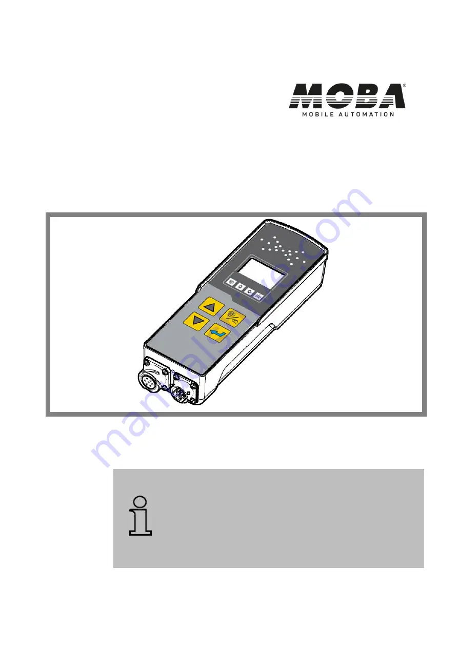
MOBA-Matic, CAN, as of Version 
V2055 

MMC-1000 

Levelling System for paver, milling machines 

and other mobile applications 


Further applicable documents: 

Specifications:  

04-03-00415 | 04-21-21010 | 04-25-10300 

04-21-10100 | 04-21-30070 | 04-60-11311 

04-21-10102 | 04-21-40110 | 

CE declaration of conformity 


ENGLISH 


Summary of Contents for MOBA-Matic MMC-1000

Page 1: ...000 Levelling System for paver milling machines and other mobile applications Further applicable documents Specifications 04 03 00415 04 21 21010 04 25 10300 04 21 10100 04 21 30070 04 60 11311 04 21 10102 04 21 40110 CE declaration of conformity ENGLISH ...

Page 2: ...ed to your dealer We will of course take up and implement any sensible suggestions and improvement proposals Some company and brand names as well as product descriptions are protected by trademark or patent law All rights reserved No part of these documents may be reproduced or transmitted for any purpose without express written permission from MOBA irrespective of the manner or the means by which...

Page 3: ...2 Other applicable documents 12 Spare parts 12 Final decommissioning disablement 13 Disposal 13 Guarantee provisions 15 Customer Service 15 2 Fundamental safety instructions 16 Intended use 17 2 1 1 Intended use of the machine 17 2 1 2 Improper use 18 Operating limits 18 Modifications and rebuilding the product 19 Responsibility of the system owner 20 2 4 1 Operating personnel 21 Special dangers 2...

Page 4: ... 42 The control and display elements of the digital controller 42 6 1 1 The LED arrow 43 6 1 2 The LC Display 44 6 1 3 The control buttons 47 The display elements of the prop Laser receiver 49 Fault indicators 52 Operating modes 52 Operating variants 53 6 5 1 Standard operation 53 6 5 2 Operation with semi automatic 53 6 5 3 Operation with auto zero setting 54 7 Installation and commissioning 55 S...

Page 5: ...setting 93 Working with the slope sensor 95 8 3 1 Description 95 8 3 2 Information for assembly 95 8 3 3 Actual value adjustment 96 8 3 4 Controlling with the slope sensor 97 Working with the Sonic Ski plus 101 8 4 1 Description 101 8 4 2 Information for the assembly and the working range 102 8 4 3 Working with the Sonic Ski plus 106 8 4 4 Controlling with the Sonic Ski plus for ground sensing 107...

Page 6: ...i 130 8 8 1 Sensor ID 130 8 8 2 Functionality 131 8 8 3 Information for assembly and installation 131 8 8 4 Electrical system 133 8 8 5 Setting up 135 8 8 6 Switching from single sensor to Big Ski 136 8 8 7 Controlling with the Big Ski 140 Working with the prop Laser receiver 142 8 9 1 Safety notices 142 8 9 2 Assembling and setting up 143 8 9 3 Controlling with the prop Laser receiver 145 9 Repai...

Page 7: ...Table of contents 7 12 Declaration of conformity 161 ...

Page 8: ...ised by every person who is assigned with the works such as e g operation troubleshooting and maintenance service care The user manual is an integral part of the product and must be passed on to third parties or subsequent owners together with the product when applicable It must be accessible to the operating personnel at the location where the product is used at all times In addition the local ac...

Page 9: ... description of these sensors is irrelevant for you Rights to amendments We have taken every effort to ensure that this user manual is correct and up to date To maintain our technological advantage it may however be necessary to initiate amendments to the product and its operation without prior notice which may in certain cases differ from this user manual In this case your MOBA supplier will alwa...

Page 10: ...ardous situation which will result in death or serious injury when it is not prevented WARNING indicates a potentially hazardous situation which could result in death or serious injury when it is not prevented CAUTION indicates a potentially hazardous situation which could result in minor or slight injury when it is not prevented CAUTION indicates a potentially hazardous situation which could resu...

Page 11: ...r many years of expertise and experience The manufacturer accepts no liability for damages resulting from Improper mounting and installation Failure to observe the operating instructions Unintended and improper use Use outside of the operating limits Use of insufficiently qualified and trained personnel Use of unauthorised spare parts and accessories Modifications to the product The current scope ...

Page 12: ...n sheet for adjusting the sensor IDs to MOBA MTSC 201 Spare parts Genuine spare parts and accessories authorised by the manufacturer serve to enhance safety The use of other parts may affect the right of the user to commission the product and may annul liability of the manufacturer for any consequences resulting from use CAUTION Risk of injury from incorrect spare parts Incorrect faulty or unautho...

Page 13: ...ection plugs mechanically destroy connection plug Disposal Packaging The products are protected for transport ex works by special packaging This packaging consists of environmentally compatible easily dividable materials and can be recycled We recommend recycling enterprises for the disposal of the packaging material Product The product must not be disposed of with household waste Dispose of the p...

Page 14: ...t in accordance with the applicable national country specific disposal regulations CAUTION Risk of injury due to improper disposal of the product Careless disposal enables unauthorised persons to use the product improperly This could result in severe injury to these persons and or third parties as well as contaminate the environment For these reasons Protect the product from access by unauthorised...

Page 15: ...is user manual contains no statement of guarantee The guarantee provisions are part of the MOBA MOBILE AUTOMATION AG MOBA Terms and Conditions of Sale and Delivery Customer Service Your MOBA Dealer will be pleased to assist with technical requests ...

Page 16: ...safety for an optimal protection of the personnel as well as for the safe and failure free operation The information should place the operators and users in the position to be able to recognise the danger in time and to prevent it as far as possible in advance The operator must ensure that all users understand and adhere to these instructions ...

Page 17: ...lising a laser or ultrasonic sensors Recording the tool inclination by utilising a slope sensor Setting various parameters for the hydraulic system performance of the machine Any use other than those listed here as well as any use that deviates from the technical data is considered to be a non intended and improper use WARNING Danger from improper use Any use that is different and or goes beyond t...

Page 18: ...s or damages Using the product with unauthorised accessories from third party manufacturers Using the product at an inadequately secured construction site area e g during road works Using the product to control machines systems or moving objects when these are not equipped with an additional control system Operating limits The MOBA Matic is designed for use in an atmosphere appropriate for permane...

Page 19: ...the product unless explicitly approved by the manufacturer Contents of the user manual Any person who is assigned with performing works at or with the product must have read and thoroughly understood the user manual before beginning work This also applies when the respective person has already worked with a product such as or similar to this one or was trained by the manufacturer or supplier ...

Page 20: ...duct is used He she must implement these in the form of operating instructions for the operation of the product These operating instructions must be stored in the immediate vicinity of the product and be accessible to persons who work at and with the product at all times The system owner must clearly define the responsibilities of the personnel for the operation of the product The system owner mus...

Page 21: ... or the manufacturer about the tasks assigned to them and about the possible dangers that may arise in the event of improper behaviour as well as those who have been given training and instructions when necessary and who have been taught about the necessary protective equipment and precautions Qualified specialist personnel Qualified specialised personnel for the purposes of the user manual are pe...

Page 22: ... hazards and avoid dangerous situations Electrical current DANGER Danger from electric current During work in the immediate vicinity of electrical systems e g overhead lines or electrical railways there is a risk of electrocution For these reasons Maintain a sufficient safety distance to electrical systems If work in such systems is absolutely necessary then always inform the relevant bodies or au...

Page 23: ... in a rotating and or linear manner may cause severe injuries and result in material damages For these reasons Always exclude people from the working range of the machine and or tool Remove objects from the working range of the machine or tool During operation do not reach into moving components The MOBA Matic must always be switched off when leaving the driver s seat or the machine Never perform ...

Page 24: ...orking range of the machine or tool Malfunction WARNING Risk of injury from malfunction Uncontrolled machine actions resulting from malfunctions of a system component could cause severe injuries to people located in the working range of the machine or result in material damages For these reasons Make certain that the machine is only operated controlled and monitored by a qualified and experienced ...

Page 25: ...ructions Missing and incomplete instructions could lead to operating errors or improper use Accidents with severe personal injuries or severe damage to property and the environment could thereby result For these reasons Observe the safety notices from the manufacturer and the instructions from the system owner ...

Page 26: ...nt safeguarding of the locations of the individual components Observe the country specific legal safety and accident prevention regulations as well as the traffic regulations that apply accordingly Faulty measurement results CAUTION Danger from faulty measurement results Faulty measurement results arising from the use of a product following a crash other non permitted loading or a modification can...

Page 27: ...age on Pin A of the 12 pin device plug socket It can be specified in a menu in the software for which applied voltage level the controller is to be switched off with depending on the wiring The installation of an emergency stop switch is the responsibility of the system owner of the machine and is strongly recommended In addition all the luminous diodes of the LED arrow of the MMC 1000 controller ...

Page 28: ...ssible at all times Familiarise personnel with accident reporting first aid and rescue equipment Keep access routes for emergency vehicles free In the event of an emergency Always do the right thing Immediately take the product out of operation Initiate first aid measures Remove people from the danger zone Inform responsible people at the place of operation Alert doctor and or fire brigade Create ...

Page 29: ...o not commission products with obvious signs of damage Report every defect as soon as it is identified Claims for damages can only be invoked within the applicable compensation periods Transport When transporting your equipment to the place of use or in the field always make certain that the product is transported in suitable transport containers and that these are appropriately secured Never tran...

Page 30: ... for this purpose if possible Avoid large temperature fluctuations during storage The formation of condensation can impair the function Always observe the storage temperature limits for products especially in the Summer when the equipment is kept in the vehicle interior Please refer to the technical data for the products for the permissible storage temperatures ...

Page 31: ... on state of the art microprocessor technology and works with a so called CAN Bus Controller Area Network This CAN Bus creates the latest standard in automotive electrics and guarantees the highest degree of system safety It also provides in its simplest form the central operation of the system and due to its modularity its gradual expansion So you can e g easily retrofit new sensors depending on ...

Page 32: ...The type label contains the CE marking 4 the device designation 2 the article number of the product 1 as well as a consecutive serial number 3 The following photograph shows an example of a type label Conformity Refer to the Declaration of Conformity section in this manual Product data Refer to the Technical data section in this manual ...

Page 33: ...ntroller and at least one corresponding sensor will be required Depending on the machine and application the operator can create their own system individually For this they simply select the sensor from the large pool of available sensors which best fulfils their respective requirements and combines it with the digital controller The CAN bus enables the simultaneous connection of several sensors t...

Page 34: ...34 Structure and function Configuration example for Big Ski 1 Digital controller 2 Distribution box 3 Slope sensor 4 Utilisable sensors Sonic Ski DUAL Sonic 5 Big Ski framework ...

Page 35: ...or The SLOS 0150 04 21 21010 slope sensor operates with a highly precise electro mechanical measuring unit and is used for the acquisition of the slope for the tool ROTS 0300 Rotary Sensor The ROTS 0300 04 21 40110 rotary sensor is a sensor for distance measurement and senses the measured values using mechanical means from an existing reference This can be both a taut and measured string as well a...

Page 36: ... in ground sensing and up to 100 cm in string line sensing An averaging is executed from the measured values of the five ultrasonic sensors of the Sonic Ski plus with ground sensing The Sonic Ski plus is not able to measure the distance to the reference with string line sensing rather additionally recognising the position of the string or an edge under the sensor heads over its entire working widt...

Page 37: ... via a distribution box In exceptional cases the averaging can also be acquired with just two sensors e g Sonic Ski plus front and rear After small unevenness and foreign bodies have already been neutralised by the averaging for every individual Sonic Ski plus the Big Sonic Ski attachment now also additionally averages and reduces bulges and small drawn out differences in height in the longitudina...

Page 38: ...ance measurement the measured value of the Dual Sonic sensor will be temperature compensated LS 3000 Laser receiver The LS 3000 04 60 11311 laser receiver is a sensor for distance measurement which works with all the common rotation lasers such as e g red light transmitters helium neon and infra red transmitters It is used among other things for the building of flat sites Power CAN Box Adapter box...

Page 39: ...he control panel now functions as an equal parallel and thereby secondary operating device 04 25 53301 MOBA Matic Case 04 06 00140 04 06 00142 04 06 00040 LS 3000 Case 04 06 00210 MOBA Matic case available in different versions For maximum 2 controller 3 Sonic Ski 2 Digi Rotary 1 slope sensor Cables and accessories LS 3000 Case available in standard version For maximum 2 Laser receiver Cable Brack...

Page 40: ...sensor CAN Controller Sensor junction Box 04 02 02624 7 pin Bayonet lock 7 pin bayonet lock 6 m Yellow yellow 2 x R 120 Coil cable extension Controller machine 04 02 02536 04 02 02535 10 pin Bayonet lock 10 pin bayonet lock 3 m 10 pin Bayonet lock 10 pin bayonet lock 6 m Coiled cable For the connection of CAN sensors on the junction box 04 02 02620 04 02 02621 7 pin Bayonet lock 7 pin bayonet lock...

Page 41: ...il the control task the instantaneous value of the controlled variable the actual value must be measured and compared with the setpoint value If there are any deviations then these must be adjusted in an appropriate manner In the case of the MOBA Matic this means Setpoint value setting with the buttons of the MOBA Matic Actual value e g via distance measurement to reference Adjustment of the tool ...

Page 42: ...ntrol and display elements of the digital controller The front of the digital controller contains all the necessary buttons some function LEDs and a LC display for the advanced operation of the system on which the current status of the system can be read out at all times The front of the digital controller can be sub divided in 4 main function groups 1 The LED arrow 2 The LC display 3 The function...

Page 43: ...deviation Controller output Large control deviation Controller output LIFT constantly on Average control deviation Controller output LIFT cycles with larger pulse width Small control deviation Controller output LIFT cycles with smaller pulse width No control deviation Controller outputs deactivated Small control deviation Controller output LOWER cycles with smaller pulse width Average control devi...

Page 44: ...The symbols of the displays have the following meaning 1 The LIFT arrow indicates that the controller output for LIFT is currently active 2 The LOWER arrow indicates that the controller output for LOWER is currently active Positive display value no prefix 3 Negative display value a prefix 4 Slope to the right a bar which slopes to the right 5 Slope to the left a bar which slopes to the left ...

Page 45: ...ive prefix i e will appear in the display The directional arrows on the lateral slope will only appear when the slope sensor has been selected as the active sensor The slope direction of the illustrated arrow is the prefix for the value of the slope sensor left slope or right slope Both arrows only jointly appear simultaneously with the display 0 0 The resolution and the physical measuring unit of...

Page 46: ...can then be assigned with a defined signal in order to for example interrupt in the controller status Also refer here to Section 11 in the Technical data of this manual Automatic lamp Lamp on Lamp flashes 1 Lamp off Automatic mode Semi automatic mode only if this optional mode has been pre set by the dealer Manual mode Direction lamps special function when working with Sonic Ski If both lamps flas...

Page 47: ...ill be amended in automatic mode with the up and or down buttons In manual mode the corresponding valve output will be controlled for the duration of the respective button pressure In the menus these serve for the selection of menu items or the setting of parameters Auto Manual button The Auto Manual button is used for switching between the operating modes manual manual mode semi automatic optiona...

Page 48: ...ength Sampling factor and Hydraulic Kit Up or Down buttons Enter button Both in the manual as well as in automatic mode pressing the UP and or the DOWN buttons together with the enter button will amend the displayed value without influence on the control system Up Down buttons In the manual mode manual mode when working with the Sonic Ski Sensor simultaneously pressing the UP DOWN buttons will sel...

Page 49: ...h a LED arrow 1 similar to the digital controller Depending on the operating mode in which the digital controller is located and which it is connected to the LED arrow of the laser receiver can have a different function In the Manual mode it is used as a positioning aid in the Automatic mode it shows the status of the valve outputs ...

Page 50: ...ikes the receiver The laser beam strikes above the centre of the receiver Displace the laser receiver and or mast upwards The laser beam strikes above maximum 2 cm from the centre on the receiver Displace the laser receiver and or mast upwards slightly The laser beam strikes the centre of the receiver The laser beam strikes below maximum 2 cm from the centre on the receiver Displace the laser rece...

Page 51: ...ol output Large control deviation Controller output LIFT constantly on Average control deviation Controller output LIFT cycles with larger pulse width Small control deviation Controller output LIFT cycles with smaller pulse width No control deviation Controller outputs deactivated Small control deviation Controller output LOWER cycles with smaller pulse width Average control deviation Controller o...

Page 52: ...controller Automatic The setpoint value for the tool will be amended in the Automatic operating mode with the up down buttons of the digital controller If a difference results from the comparison of the measured value and the set setpoint value then digital controller will control the outputs independently itself until this difference is compensated Flashes Semi automatic 1 In the operating mode S...

Page 53: ... in conjunction with the Up button or the Down button the displayed setpoint can be amended without influencing on the tool position 6 5 2 Operation with semi automatic The setpoint adjustment with the up down buttons is executed in the operating modes Semi automatic and Automatic consecutively in 1 mm steps as long as the affected button remains pressed In the operating mode Semi automatic no con...

Page 54: ...ure on the up or the down buttons by 2 mm in the corresponding direction The tool is therefore traversed according to the default settings in the controller After 5 seconds the setpoint value will be automatically set to zero and the sensor offset will be set once in accordance with the setpoint amount The description of the operation of the different sensors in this manual is based on the standar...

Page 55: ...the product and errors occurring during the installation can impair the function and safety of the machine and thus lead to dangerous situations or material and property damages For these reasons Installation and initial commissioning are only to be executed by personnel with the required training and qualifications Always observe the instructions of the machine manufacturer If there are not suffi...

Page 56: ...cation possibilities for the MOBA Matic and the diversity of different machines available only general instructions for the assembly site and installation position for the various components can be given here The digital controller A bracket is provided as an accessory Install the bracket on a position that enables a comfortable operation and from which the tool and or the adjusting device of the ...

Page 57: ...g machine this is preferred in the lower area of the machine e g on the milling drum housing on the transverse traverse between the tow arms for blacktop pavers Four fixing holes are provided in the fastening plate of the sensor for the assembly works The plug connections must be freely accessible to ensure that the connection of the connecting cable is easily possible IMPORTANT Observe the direct...

Page 58: ...ng pipe with a round mounting for the MOBA grade sensors should be adjustable in height swivelling and can be moved horizontally Refer to the example below The round sensor head and the possibility for swivelling the bracket arm enables the sensors to be adjusted without any problems for every reference e g Sonic Ski plus in the ground or string line sensing This bracket can look different dependi...

Page 59: ...n the direction of travel Using an M6 x 12 hexagon socket screws 1 the junction box 2 will be initially assembled on the mounting plate 3 Then the mounting plate 3 will be assembled using a M8 star knob screw 4 to one of the central sliding brackets 5 When assembling the Big Sonic Ski on the right hand side of the machine the box should be assembled on the inside of the support mechanics so that t...

Page 60: ...ation and commissioning The laser receiver The assembly of a laser receiver on the mast pipe is relatively simple 1 Open the mounting clamp 2 Slide the laser receiver over the mast pipe 3 Close the mounting clamp ...

Page 61: ...ured that this is positioned in the typical vertical working position of the tool An adjustable assembly position on the mast is ideal so that the variable working position of the tool is guaranteed with the vertical position of the mast An adjustable inclinable mast also serves to simplify the safety and handling e g The best installation location for connecting a laser mast on the milling machin...

Page 62: ...ology requires the completion of the Bus via resistors In order to make the wiring as easy as possible MOBA has already provided a part of its sensor cable already with these terminating resistors In order to differentiate this cable from other cables the jacket material is coloured yellow and the cable glands on the connectors are grey The different connection variants are shown in the following ...

Page 63: ...Installation and commissioning 63 Connection diagram without cross connection MACHINE CONNECT ONLY THE left OR right Sonic Ski CAN Rotary LS 3000 Laser receiver and other MOBA CAN sensors Slope sensor ...

Page 64: ...ion and commissioning Connection diagram with cross connection via junction boxes Sonic Ski CAN Rotary LS 3000 Laser receiver and other MOBA CAN sensors Always CONNECT BOTH sides Slope sensor Alternative connection ...

Page 65: ...Ski CAN Sonic Ski plus CAN Sonic Ski plus CAN PWM 5 04 21 40110 Rotary sensor 6 04 60 11311 Laser receiver 7 04 03 00422 Junction box left 8 04 03 00423 Junction box right Cable Article number Designation a 04 02 02624 Coil cable CAN with 2x1 20R Bus resister 6m b 04 02 02560 Coil cable DLS II CAN machine 3m fully wired c 04 02 02561 Coil cable DLS II CAN machine 3m without CAN wiring d 04 02 0262...

Page 66: ...d adjustment of the control parameters on the valves and the hydraulic system of the machine at the factory If the system has been retrofitted please contact your MOBA dealer so that they can support you during the commissioning of the MOBA Matic In the context of this procedure the adjustment of the control parameters on the valves and the hydraulic of your machine among others must still be exec...

Page 67: ...st only be operated by trained and instructed people Fundamental principles WARNING Danger due to improper operation Improper operating can lead to serious personal injuries or property or material damages For these reasons Only permit personal with the required qualifications to operate the product Always execute all the operating steps in accordance with the specifications in these operating ins...

Page 68: ... on Inspect all of the components of the system for any obvious damage the unions of the connecting cable for correct fitting and the sensors for safe and correct assembly Always ensure that when you turn on the MOBA Matic that person or object is present in the area of the tool or in the area of moving parts for controlling the tool 8 1 1 Switching on and switching on message Switch on the supply...

Page 69: ...4 function lamps will therefore be controlled for approximately 2 seconds Should any signs icons or characters be missing on the display or luminous diodes do not illuminate then notify the customer service 8 1 2 Controller side display After the display test the display will indicate on which side of the machine the controller is located Right hand side Left hand side or ...

Page 70: ...th direction lamps also flash in this presentation The controller subsequently switches automatically to the working mode Example of sensor identification for the Sonic Ski Plus If the sensor should be replaced or has been removed then the controller will indicate this clearly with the below represented No message Is should be indicated to the user when switching on that the sensor has been exchan...

Page 71: ...r reference for all following setpoint value specifications The process is referred to as zero adjustment For this 1 Place the bottom edge of the tool manually to the adjustment height i e on the level which is decisive for the forthcoming work project layer thickness milling depth level of the plane to be finished etc 2 Position the grade sensor s on the reference If you are working with laser re...

Page 72: ...down until the actual value display Set is displayed and after another approx 2 seconds the value springs to 0 0 The current measured value of the grade sensor actual value will be acquired as the setpoint value and both variables will be assigned the value 0 0 No control deviation exists If a sensor on the controller has been disconnected and there is no other sensor connected then No Sen on the ...

Page 73: ...Display value The displayed setpoint value can be amended by actuating the Enter button together with the UP and or DOWN buttons without influencing the tool position The switching between Manual Semi automatic and Automatic is executed revolving with the A M button WARNING Tool will be traversed The tool will therefore be traversed The display will show the amended setpoint value Keep persons awa...

Page 74: ...splay value The displayed setpoint value can be amended by actuating the Enter button together with the UP and or DOWN buttons without influencing the tool position The switching between Manual Semi automatic and Automatic is executed revolving with the A M button Manual LED off Control outputs active No setpoint adjustment Semi automatic LED off Control outputs are inactive Setpoint value adjustm...

Page 75: ...O ZERO Setpoint value adjustment Use the UP DOWN buttons to select the setpoint value amendment The setpoint value amendment will be executed in automatic operating mode after respectively pressing again in 2 mm steps ...

Page 76: ...ll initially go into the manual operating mode with every switching on also when the Automatic operating mode was switched on when the system was turned off Always still turn the MOBA Matic to the Manual operating mode even when leaving the machine For longer downtime periods and at the end of the works the power supply must be disconnected and the system dismantled or be reliably secured against ...

Page 77: ...are irrelevant in the currently related sensor combination will also not be displayed when calling up the user menu to prevent unnecessary confusion for the operator It may be that the user menu comprises only 2 menu items when called up in other cases respectively with 7 or 8 menu points The following will describe all menu items in a sequence in which you can create a complete equipped and appro...

Page 78: ...the Enter button Use the same button combination will also switch from one parameter to the next By pressing the UP or the DOWN buttons the parameter values will be set or function modes will be switched The user menu can be exited again at any time by pressing the A M button again Alternatively you can switch again by utilising the Enter button in the menus ...

Page 79: ...Operation 79 Graphical representation of the user menu ...

Page 80: ...tton and the Enter button several times until the display between the abbreviation for the sensor selection S S and the identifier of the active sensor here rtY for the rotary sensor switches back and forth By actuating the UP and DOWN buttons alternatively possible other sensors will be displayed here the Big Ski but are still not activated Working mode will be switched back to by actuating the A...

Page 81: ...ely for each type of sensor and will then when a sensor is changed be automatically loaded Should the MOBA Matic operate roughly in automatic mode then the sensitivity on the corresponding digital controller must be reset If the MOBA Matic operates too sluggishly in automatic mode then sensitivity must be increased on the corresponding digital controller Your MOBA dealer has the possibility to ame...

Page 82: ...iation for the sensitivity setting SE and the last set value preset 6 The value will be increased and or reduced by actuating the UP or DOWN buttons here Setting to the value 7 Working mode will be switched back to by actuating the A M button If no button is actuated then the controller automatically switches back to this position after 5 seconds ...

Page 83: ... 0 0 12 1 50 5 0 1 4 26 0 5 0 0 10 1 30 6 0 1 2 21 0 6 0 0 08 1 10 7 0 1 0 16 0 7 0 0 06 0 90 8 0 0 8 11 0 8 0 0 04 0 70 9 0 0 6 6 0 9 0 0 02 0 50 10 0 0 4 1 0 10 0 0 00 0 30 Dual Sonic Sensor Sonic Ski plus Big Sonic Ski Cable sensor and rotary sensor Sensitivity Dead band Prop band 1 0 0 25 4 00 2 0 0 22 3 61 3 0 0 19 3 22 4 0 0 17 2 83 5 0 0 14 2 44 6 0 0 11 2 06 7 0 0 08 1 67 8 0 0 06 1 28 9 0...

Page 84: ...14 0 4 3 4 12 0 4 2 4 12 0 5 3 0 10 0 5 2 0 10 0 6 2 4 8 0 6 1 4 8 0 7 2 0 6 0 7 1 0 6 0 8 1 6 5 0 8 0 8 5 0 9 1 2 4 0 9 0 6 4 0 10 1 0 3 0 10 0 4 3 0 Dual Sonic Sensor Sonic Ski plus Big Sonic Ski Cable sensor and rotary sensor Sensitivity Dead band Prop band 1 0 40 1 60 2 0 30 1 40 3 0 20 1 20 4 0 14 1 00 5 0 10 0 80 6 0 06 0 60 7 0 04 0 50 8 0 02 0 40 9 0 02 0 30 10 0 00 0 20 Slope sensor ...

Page 85: ...e current measured cross slope will be displayed in the operator menu as the third point Actuate the A M button and the Enter button at the same time The display shows for a short moment approx 1 second the abbreviation for the display of the cross slope Slo and then flashes with the current measured value of the cross slope sensor Work mode will be reset by actuating the A M as well as the UP and...

Page 86: ...ing Hd Manual mode setpoint assignment is executed by using keyboard entries Actuate the A M button and the Enter button several times at the same time until the display between the abbreviation for the setpoint assignment SP and the current control type here A for 3D setpoint assignment By actuating the UP or DOWN button the other setpoint assignment set here Hd for setpoint assignment for input ...

Page 87: ...al errors reference string is torn etc To prevent these unintended measurement errors and the resulting extreme controlling actions of the machine the measured values of all grade sensors can be allocated with a so called control window If a control deviation occurs which is greater than the range set here then this deviation will be detected as an error In this case a warning symbol Measured valu...

Page 88: ...the working point Setting the control window Simultaneously actuate the A M button and the Enter button several times until the display between the symbol for the control window setting and the last set value preset OFF is also deactivated switches back and forth By pressing the UP or DOWN button this variable for the control window will be increased or reduced here setting to the value 8 0 4 0 cm...

Page 89: ... is activated with the control basic setting and when a grade sensor is selected in the Sensor selection menu item Change in height of the sensor x sampling factor change in height of the tool Determining the sampling factor Before a sampling factor can be entered this must of course be initially determined With the necessary physical principles here In most of the applications for which the MOBA ...

Page 90: ...linder can be on every optional position here and has no influence for the sampling factor If the grade sensor is fixed on Position 1 i e directly above the tool centre point then a change in height for the tool corresponds exactly to the change in height of the sensor The sampling factor is exactly 1 00 for this special case Pivotal point Tool Hydraulic cylinder Ground Pivotal point Tool Hydrauli...

Page 91: ...nd tool centre point must always be larger than 1 00 in order to compensate for this situation The change in height of the sensor on sensor Position 3 is however significantly greater than that of the tool Therefore the sampling factor must be smaller than 1 00 in this case as the sensor is mounted farther away from the pivotal point as the tool itself The sampling factor can be calculated with th...

Page 92: ... and forth between the abbreviation for the sampling factor POS and the preset value 1 00 The value for the sampling factor will be adjusted by actuating the UP or DOWN button Working mode will be switched back to by actuating the A M button If no button is actuated then the controller automatically switches back to this position after 5 seconds ...

Page 93: ...ossible number of hydraulic kits can be limited in the basic setting of the digital controller by your MOBA dealer The stored settings for the respective machine can then be loaded via this menu item The change of the hydraulic dataset has a direct influence on the control It is possible that the control of your machine only works with a different dataset or only insufficiently therefore only make...

Page 94: ... hydraulic kit setting tYP and the last set hydraulic kit setting preset 1 There will be a switching between the saved hydraulic kits when the UP or DOWN buttons are actuated here Adjustment of the hydraulic kit 2 Working mode will be switched back to by actuating the A M button If no button is actuated then the controller automatically switches back to this position after 5 seconds ...

Page 95: ...y The slope sensor must be assembled on a machine part which implements all slope amendments for the tool in the same dimension In the case of a road milling machine this is preferred in the lower area of the machine e g on the milling drum housing on the transverse traverse between the tow arms for blacktop pavers Four fixing holes are provided on the fastening plate of the sensor for the assembl...

Page 96: ...t here Procedure Actual value adjustment during automatic mode The system is located in automatic mode AUTO function lamp is on Here in our example the control works with a setpoint value setting of 2 45 The results of the work will be measured again with a highly accurate digital spirit level According to the above presentation this determined actual value is actually only 2 30 Press the enter ke...

Page 97: ...ment of the plank setting angles pitch on the paver 8 3 4 Controlling with the slope sensor The slope sensor and the digital controller are assembled the cables are connected and the digital controller is supplied with voltage After the switch on message has been issued digital controller indicates the sensor ID If the message for the connected sensor changes automatically after a short period of ...

Page 98: ...here left If the sensor is being operated for the first time or has been previously replaced then the sensor ID must be acknowledged by pressing a preferred button WARNING Tool will be traversed This step must be executed at all times In the event of non compliance the tool will traverse to an undefined position tool when changing over to automatic mode 1b 2 1a ...

Page 99: ...tton must now be pressed to acquire the slope of the tool as the setpoint value The SEt message appears in the display here 5 35 right slope The actual value then appears on the display again Actuate the A M button to switch over to automatic mode The function lamp AUTO is on The controller now displays 5 35 as the setpoint value It will now be adjusted to this value A control deviation will be sh...

Page 100: ...ctual value at any time with the A M button to inspect the slope of the tool The automatic control of the valve is then however switched off here 6 00 right slope Sensitivity setting If the system works in automatic mode too sluggishly then the sensitivity setting should be amended accordingly The procedure is described under item 8 2 2 of this user manual 8 7 ...

Page 101: ...ent and works without contact with 5 ultrasonic sensors A sixth sensor is used for temperature compensation Sensor identification When the system is switched on or with a sensor change the illustration in the controller display alternates changes between the design for the Sonic Ski and the abbreviation for the sensor ...

Page 102: ...e g on the tow arm for pavers or on the chassis for milling machines Procedure 1 Loosen the clamping screws on the securing pipe 2 Insert the round centring spigot on the top side of the sensor housing vertically in the securing pipe 3 Rotate the sensor housing according to the moving direction 4 Secure the centring pivot of the sensor with the clamping screws 1 Securing pipe 2 Clamping screws 3 C...

Page 103: ...or string line sensing Align the sensor at the centre of the string In order to display the string under the sensor heads of Sonic Ski plus in the display as lateral the sensor must be built in on both sides in such a way that so it is represented as in the sensor symbol i e Respectively with the connecting plug to the left as seen in direction of travel The string will only initially be recognise...

Page 104: ...udinal direction averaging by Sonic Ski with ground sensing The Sonic Ski must operate in a lateral direction with string line sensing so that the full working width of 25 cm is available Conventional simple sensing Averaging via the Sonic Ski Resulting road coating Resulting road coating Ground sensing String line sensing Moving direction ...

Page 105: ...his range The Sonic Ski should be aligned to approx 35 cm distance to the reference The string will only initially be recognised as a reference point with a diameter of 3 mm At this point we should once again expressly refer to the preassigned working directions for string and ground sensing and the optimal working range of Sonic Ski Both defaults must be strictly adhered to in order to achieve th...

Page 106: ...to display the actual value then the system is ready for operation If the sensor is being operated for the first time or has been previously replaced then the sensor ID must be acknowledged by pressing a preferred button Execute the sensor selection as described in Section 4 when applicable Procedure Acknowledgement of the sensor ID The digital controller displays the sensor identification for the...

Page 107: ...i to a distance of 35 cm above the ground the actual value display must be constantly on The two arrows are irrelevant with ground sensing Now press the Enter key In the event of a brief press SEt appears on the display The current actual value is then acquired as the setpoint value If the button is pressed for longer than 1 5 seconds then the display will change from SEt to 0 0 The actual value a...

Page 108: ...nual mode can be switched back to at any time with the A M button The automatic control of the valve will therefore be switched off Operating variants Adjustment and display of the setpoint value depending on the operating version as different also refer to Section 8 1 4 Differences between the control variants in this manual 8 9 ...

Page 109: ...e will be activated by simultaneously pressing the UP DOWN buttons The string lamp is on Align the tool to the working position for the zero adjustment with the UP DOWN buttons on the controller or the operator unit on the machine Align Sonic Ski to a distance of 35 cm above the string the actual value display must be constantly on Seil ca 35cm 3 4 1 2 Approximately 35 cm String ...

Page 110: ...ated again Now press the Enter key In the event of a brief press SEt appears on the display The current actual value is then acquired as the setpoint value If the button is pressed for longer than 1 5 seconds then the display will change from SEt to 0 0 The actual value and the setpoint are now set to zero Automatic mode will be switched back to with the A M button The function lamp AUTO is on The...

Page 111: ...ating variants Adjustment and display of the setpoint value depending on the operating version as different also refer to Section 8 1 4 Differences between the control variants in this manual Sensitivity If the system works in automatic mode too sluggishly then the sensitivity setting should be amended accordingly Refer to item 8 2 2 of this manual Control window A control window is active when op...

Page 112: ...lues by using mechanical means from an existing reference This can be both a taut and measured string as well as a surface e g a road surfacing Sensor identification When the system is switched on or with a sensor change the illustration in the controller display alternates changes between the abbreviation for rotary and the abbreviation for sensor ...

Page 113: ...y for operation If the sensor is being operated for the first time or has been previously replaced then the sensor ID must be acknowledged by pressing a preferred button Otherwise execute sensor selection as described in Section 8 2 1 Acknowledgement of the sensor ID The digital controller shows the sensor identification If the sensor is being operated for the first time or has been previously rep...

Page 114: ...ent references The sensing tube will be utilised for sensing the string the sensing ski for the ground Assembling the sensing tube on the sensing arm 1 Loosen the nut 1 on thread 2 of the sensing tube 3 2 Slide the sensing tube 3 into the securing ring 4 of the sensing arm 5 3 Secure the sensing tube 3 with the nut 1 ...

Page 115: ...1 Remove the locking pin 5 from the bolt 3 of the sensing ski 1 remove bolt 3 2 Guide the ski fastening 2 over the locking pin 6 of the sensing arm 4 3 Insert the bolt 3 through the ski fastening 2 and the locking pin 6 4 Secure the bolt 3 with the splint pin 5 ...

Page 116: ...rotary sensor 1 Rotate the flattened part of the axis to the opposite side of the sensor connector 2 Loosen the clamping screw on the sensing arm 3 Insert the sensing arm on the axis 4 Securely tighten the clamping screw on the flat part of the axis ...

Page 117: ...ssis above the milling drum with a milling cutter Procedure 1 Loosen the clamping screws on the securing pipe 2 Insert the round centring spigot on the top side of the sensor housing vertically in the securing pipe 3 Rotate the sensor housing according to the moving direction connecting plug in moving direction 4 Secure the centring pivot of the sensor with the clamping screws 1 Securing pipe 2 Cl...

Page 118: ...in the perfect angle for the measured value recording Also refer to the diagrams below Sensing the string The sensing tube is implemented for sensing the string Align the counter weight by screwing in or unscrewing so that the sensing tube applies a slight pressure on the string from above If the string to be utilised as a reference indicates to little tension then there is a possibility to introd...

Page 119: ...l be switched back to with the A M button The AUTO function lamp is off Align the tool to the working position for the zero adjustment with the UP DOWN buttons on the controller or the operator unit on the machine The sensing tube must apply slight pressure on the string This can be set with the counterweight Now press the Enter key In the event of a brief press SEt appears on the display The curr...

Page 120: ...N buttons to amend the setpoint value in automatic mode to be therefore able to acquire corrections Manual mode can be switched back to at any time with the A M button The automatic control of the valve will therefore be switched off Reaction force for sensing tube The reaction force of the sensing tube changes with the adjustment Adjustment and display of the setpoint value depending on the opera...

Page 121: ...s SEt appears on the display The current actual value is then acquired as the setpoint value If the button is pressed for longer than 1 5 seconds then the display will change from SEt to 0 0 The actual value and the setpoint are now set to zero Automatic mode will be switched back to with the A M button The function lamp AUTO is on The controller stops the tool on the set value Use the UP DOWN but...

Page 122: ...refer to Section 8 1 4 Differences between the control variants in this manual Sensitivity If the system works in automatic mode too sluggishly then the sensitivity setting should be amended accordingly Refer to item 8 2 2 of this manual Control window A control window is active when operating the digital controller with the rotary sensor The setting of the control window can be read out under the...

Page 123: ...ncreasing intervals When working with the Dual Sonic sensor there must therefore be a free space of 20 cm retained around the sound beam axis to prevent disturbing reflections in the entire specified working range Working range The optimal working range for the Dual Sonic sensor is between 30 cm and 50 cm The Dual Sonic sensor should be set to approx 35 cm distance to reference Approximately 35 cm...

Page 124: ...as described in the section for assembling and setting up over the reference position Press the Enter button The actual setpoint value will be acquired as the setpoint value Press the Enter button an hold for approximately 2 seconds Actual value and setpoint will be set to 0 0 Switch controller with the Auto manual key into the Automatic operating mode The function lamp AUTO is on The controller s...

Page 125: ...in conjunction with the milling machine It is used for the distance measurement and has a measuring range of 50 cm Sensor identification When the system is switched on or with a sensor change the illustration in the controller display alternates changes between the sign for the wire rope and the abbreviation for the sensor ...

Page 126: ...e can be pulled out by approx 50 cm and is then hooked and or fixed on the space provided on the side plate of the milling machine In the milling application the wire of the wire rope sensor should be pulled out by approx 3 cm with the stop side shield hanging in order to have the maximum measuring range of the sensor available The wire of the wire rope sensor should always be mounted individually...

Page 127: ...me to display the actual value then the system is ready for operation If the sensor is being operated for the first time or has been previously replaced then the sensor ID must be acknowledged by pressing a preferred button Otherwise execute sensor selection as described in Section 8 2 1 Acknowledgement of the sensor ID The digital controller shows the sensor identification If the sensor is being ...

Page 128: ... position for the zero adjustment with the UP DOWN buttons on the controller or the operator unit on the machine Inspect the wire attachment Is there a sufficiently large working range available for the planned application Now press the Enter key In the event of a brief press SEt appears on the display The current actual value is then acquired as the setpoint value 3 4a 1 2 ...

Page 129: ...t any time with the A M button The automatic control of the valve will therefore be switched off Operating variants Adjustment and display of the setpoint value depending on the operating version as different also refer to Section 8 1 4 Differences between the control variants in this manual Sensitivity If the system works in automatic mode too sluggishly then the sensitivity setting should be ame...

Page 130: ...he representation in the in the display of the controller alternates changes between a numerical representation the numbers 1 to 3 are used to represent the occupied connector of the Big Ski connection box and or the occupied Big Ski connector for the in house wired up CAN Bus wired machine and the abbreviation for sensor ...

Page 131: ...installation Mechanical systems Your MOBA dealer retains installation instructions ready for you in which the assembly of the mechanics of the Big Sonic Ski is described in detail Also refer to Section Additionally applicable documents The mechanical design plays a very important role when implementing Big Ski systems However as these are individually designed by the dealer or customer only a basi...

Page 132: ...ed at an angle refer to the sketch This thereby simplifies the alignment of the individual sensors via the reference it is not unusual in practice for Sonic Ski to be even positioned in front of and behind the machine to also ensure the safe sensing of the reference The distances between the sensors are ideally equal X1 X2 The centre sensor is to be placed where it would be attached when also only...

Page 133: ... controller for the sensor ID is always carried out from the front to the rear in moving direction On Positions 1 and 3 i e front and rear only ultrasonic sensors may be implemented In this case the 3 sensors will be connected via a special Big Ski Junction Box with the corresponding coded connectors connected with the controller ...

Page 134: ... Initially connect the digital controller to the input of the distribution box Then connect the desired sensor combination as shown schematically below at the outputs of the junction box Allowing for the moving direction the front sensor will be connected to output 1 the centre sensor at output 2 and the rear to output 3 This sequence also applies for the numeric representation in the display of t...

Page 135: ... mode Therefore all Sonic Skis must be aligned as longitudinal when to the moving direction when working to achieve an optimum result Every one of the Sonic Ski sensors must be aligned at a distance of 30 cm to 40 cm to the reference Ground Approximately 35 cm ...

Page 136: ...rated for the first time or its sensor combination has been previously replaced then the sensor ID must be acknowledged by pressing a preferred button Otherwise execute sensor selection as described in Section 8 2 1 Is the sensor is selected as the active Big Ski lights up the function lamp rope of the digital controller The digital controller shows the sensor ID here averaging from Sonic Ski fron...

Page 137: ...of a narrow asphalt installation before the front ski no longer measures the correct reference measures transition edge from milling area to the old road surface Single sensor selection Activating manual mode Press Auto Manual and Enter buttons at the same time Select the sensor with UP and DOWN buttons Press Auto Manual buttons Function lamp goes out the centre sensor is selected 1 2 3 4 4a ...

Page 138: ...ue to moving tool When switching from single sensor application to Big Sonic Ski the actual value of the single sensor is automatically taken over as actual value for the Big Sonic Ski There are no deviations of the setpoint or the actual value However when switching vice versa from Big Sonic Ski to single sensor application the single sensor s value is not adjusted i e there may be an abrupt chan...

Page 139: ...Manual and Enter buttons at the same time Select the sensor with UP and DOWN buttons Press Auto Manual buttons Function lamp illuminates the Big Ski 123 is selected After the button is pressed again the mean value from the measured signals of all 3 connected sensors on Big Ski are represented 1 2 3 4 4a ...

Page 140: ...he tool to the working position for the zero adjustment with the UP DOWN buttons on the controller or the operator unit on the machine Align all Sonic Skis at a distance of 35 cm from the ground Now press the Enter key In the event of a brief press SEt appears on the display The current actual value is then acquired as the setpoint value ca 35cm 1 2 4a 3 Ground Approximately 35 cm ...

Page 141: ...ed back to at any time with the A M button The automatic control of the valve will therefore be switched off Operating variants Adjustment and display of the setpoint value depending on the operating version as different also refer to Section 8 1 4 Differences between the control variants in this manual Sensitivity If the system works in automatic mode too sluggishly then the sensitivity setting s...

Page 142: ...m into the eyes of other people Always operate the laser transmitter well above eye level Improper assembly CAUTION Risk of injury from improper mounting The laser transmitter and laser receiver must be completely assembled at a considerable height above the ground Assembling with unsuitable auxiliary aids can lead to injuries For these reasons Never climb on the machine and the mast Always utilis...

Page 143: ...the machine There must not be any reflecting surfaces in the area of the laser beam windows automotive glazing etc In order to minimise the occurrence of reflections it is advisable to cover the laser transmitter to the actually required circular section The specified operating range of the laser transmitter must not be exceeded observe environmental influences Working point Set up a suitable lase...

Page 144: ...lso refer here to Section 6 2 Display elements of the prop Laser receiver Only in this way can the setpoint be amended subsequently when working on the full range of 14 cm The working point can in principle be acquired at any preferred point of the laser receiver Depending on the planned application this can even be useful With an asymmetric working point the available adjustment range of a direct...

Page 145: ...sor as described in the section for assembling and setting up over the reference position Press the Enter button The actual setpoint value will be acquired as the setpoint value Press the Enter button an hold for approximately 2 seconds Actual value and setpoint will be set to 0 0 Switch controller with the Auto manual key into the Automatic operating mode The function lamp AUTO is on The controll...

Page 146: ...ts this will lead to sluggishness in the mechanical systems The drain holes must be regularly inspected for soiling Cleaning and drying Cleaning works on the MOBA Matic can also be carried out by lay people when they adhere to the following specifications Devices 1 Turn the MOBA Matic off 2 Apply customary cleaner for synthetics on a soft lint free and moist cloth 3 Use hand hot water 4 Clean the ...

Page 147: ...connector contacts and the threads of the plug in connectors and cable fasteners are to be protected to prevent bad contacts to keep them free of dirt grease asphalt or other foreign materials and to protect them against moisture Blow off soiled plug connectors on the connecting cable Repair In the event that the device becomes damaged or worn contact your MOBA dealer ...

Page 148: ...g messages can in some cases be excluded due to the strict compliance with the specifications in the user manual This then saves the hassle and costs of unnecessary downtime The devices and associated components may only be opened in the framework of a reconfiguration and when they are therefore explicitly requested to be Errors must only be remedied and eliminated by an authorised professional el...

Page 149: ...ured value of the active sensor is outside the permissible measuring range Outputs in the automatic operating mode are locked Inspect the sensor alignment and or position Replace the sensor 3 Measured value of the active sensor is outside the set control window Outputs in the automatic operating mode are locked Inspect the sensor alignment and or position Reset the sensor rop dEF Slo dEF Controlle...

Page 150: ...rror message with any preferred button Reacquire the working position zero point and setpoint E 3 E 4 E 5 Data loss of the battery independent saved parameters Outputs in the automatic operating mode are locked Acknowledge the error message with any preferred button The machine parameters will therefore be set to the basic values Re adjust if necessary Enter the working position zero point and set...

Page 151: ...pply is required for fault correction switch to Manual operating mode CAUTION Risk of injury from improper fault correction Improper troubleshooting can lead to personal injuries or material damage For these reasons Only permit personal with the required qualifications to implement fault correction Do not work hastily during fault correction Observe the country specific legal safety and accident p...

Page 152: ...dimensioned technical drawing of the device a description of the interfaces and some basic technical information Rights to amendments To maintain our technological advantage it may however be necessary to initiate amendments to the product without prior notice which may in certain cases differ from this data sheets In this case your MOBA supplier will always have a current copy of the data sheet a...

Page 153: ...C Storage temperature range 25 C 85 C Protection class IP67 Weight 1 1 kg Connector pin assignment 12 pin Device plug bayonet connection A Input external manual B CAN C CAN D Input side detection E Input grade slope changeover F Output alarm G n c not consigned H n c J Output lowering K Output raising L Operating voltage M Operating voltage 7 pin Device connection box bayonet connection A Operatin...

Page 154: ...Grade Pin open n c Grade sensor Grade Input External manual Pin on mass Stops the automatic Pin on Bat Stops the automatic Pin open n c Automatic free Input Side detection Pin on mass right Pin on Bat left Pin open n c left The logic of the input External manual can be amended by using the CAN configuration message or in the advanced menu of the controller parameters ...

Page 155: ... C Protection class IP67 Shock resistance 15 g 15 ms DIN EN 60068 2 29 Weight Approx 1 9 kg Pin assignment CAN Schnittstelle CAN interface ISO 11898 24V 125kBit sec 7 pin Device plug connector bayonet connection Links left A Supply voltage B CAN C Supply voltage D CAN E Adr 1 IN F Adr 2 IN G Shield Rechts right A Supply voltage B CAN C Supply voltage D CAN E Out supply voltage F n c G Shield Remar...

Page 156: ... temperature range 25 C 85 C Storage temperature range 40 C 85 C Working range Ground sensing 20 150 cm String line sensing 20 100 cm Technical data Storage temperature range 25 C 80 C Protection class IP67 Weight approx 2 1 kg Pin assignment CAN interface ISO 11898 24 V 125 kBit sec 7 pin Device plug connector bayonet connection A Operating voltage B CAN C Operating voltage D CAN E Adr 1 F Adr 2 ...

Page 157: ...l resolution 0 1 Reproducibility 0 1 Working temperature range 10 C 85 C Storage temperature range 25 C 85 C Technical data Measurement range 340 Protection class IP67 Weight approx 1 2 kg Pin assignment CAN interface ISO 11898 24 V 125 kBits sec 7 pin Connector bayonet connection A Operating voltage B CAN C Operating voltage D CAN E Adr 1 F Adr 2 G Shield Remark ...

Page 158: ...range 50 cm CAN interface ISO 11898 24 V 125 kBit sec Working temperature range 10 C 60 C Storage temperature range 25 C 75 C Protection class IP54 Weight approx 1 75 kg Pin assignment 7 pin Device plug connector bayonet connection A Operating voltage B CAN C Operating voltage D CAN E Address1 F Address2 G Shield Remark ...

Page 159: ...ht approx 1 4 kg Protection class IP67 Method of tightening M6 threaded holes on the rear side Pin assignment A Operating voltage B Operating voltage C Raise D Lower E n c F n c G n c H n c I n c J ext Manual 1 10 1 Operating voltage 2 Raise right 3 ext Manual 4 Raise left 5 Operating voltage 6 n c 7 Lower right 8 Operating voltage 9 Lower left 10 n c Remark Also available without Vögele plug Orde...

Page 160: ...ge 40 70 C Protection class IP 67 Weight Approx 1 8 kg Mast diameter Up to 46 mm Remark Integrated positioning aid Dynamic adjustment of the sensitivity with changing light conditions Technical data Operating voltage 10 30 V DC Current consumption Approx 260 mA 12 V Approx 135 mA 24 V Working diameter 600 m transmitter dependent Receiving angle 360 Receiving range 290 mm Measurement range 284 mm R...

Page 161: ...Declaration of conformity 161 12 Declaration of conformity ...

Page 162: ...162 Declaration of conformity ...

Page 163: ...Declaration of conformity 163 ...

Page 164: ...164 Declaration of conformity ...

Page 165: ...Declaration of conformity 165 ...

Page 166: ...166 Declaration of conformity ...

Page 167: ...Declaration of conformity 167 ...

Page 168: ...168 Declaration of conformity ...

Page 169: ...measured slope from a slope sensor Minimum pulse Minimum triggering pulse which is required to traverse a hydraulic cylinder in the smallest possible way Maximum pulse Trigger pulse which defines the maximum permissible working speed of a hydraulic cylinder Zero adjustment The current measured value of the grade sensor will be assigned the value of 0 0 and at the same time acquired as the setpoint...

Page 170: ...ed value setpoint Setpoint value The preset target figure from the operator which should be achieved by a control loop and complied with Actuator Sets the controller signals in usually mechanical work that means movement e g a valve that opens or closes Dead band Symmetrical around the working point positioned range in which no control of the output is executed It serves the purpose of achieving a...

Page 171: ...Notes ...

Page 172: ...5 630 0761 Fax 39 045 630 1342 E mail mobaitalia moba it MOBA Mobile Automation Ltd 10a 10b Pegasus Way Haddenham Business Park Haddenham Buckinghamshire HP17 8LJ Great Britain Phone 44 184 429 3220 E mail ilewis moba de MOBA Brasil Belo Horizonte MG Brasi Phone 55 31 7513 4959 E mail mobadobrasil moba de Novatron Finland 33960 Pirkkala Finland Phone 358 0 3 357 26 00 E mail sales novatron fi MOBA...

Reviews: