40
xtra
-
Installation & Servicing
SERVICING
51 GAS VALVE ADJUSTMENT
The boiler contains 2 Modules with individual gas valves. Both
must be adjusted.
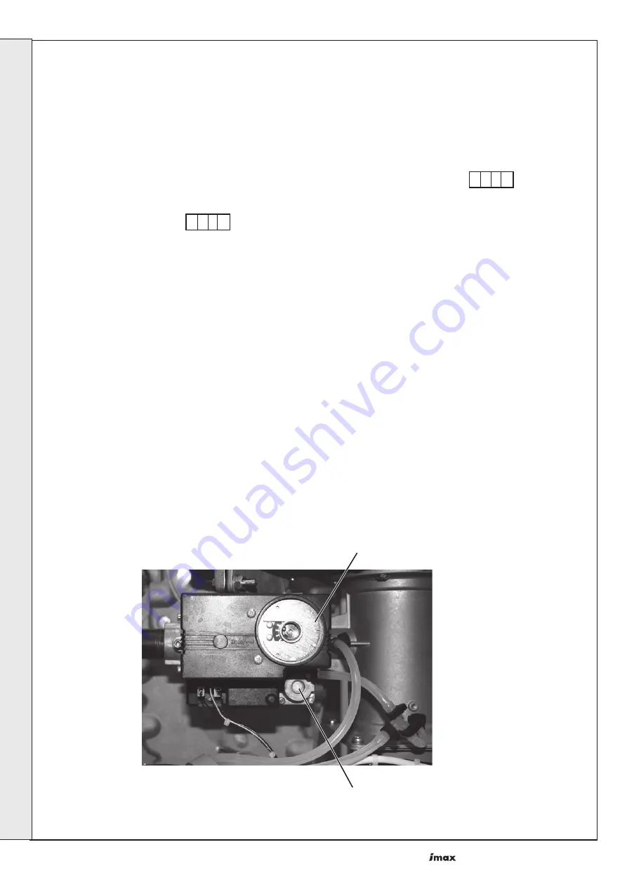
Maximum rate adjustment
1.
Switch the boiler on and operate for 10 minutes.
2.
To ensure the boiler operates at maximum rate without
modulating set the fan speeds to maximum.
3.
Remove the outer fascia panel on the Slave Module (see
Frame 52).
4.
To set the fan speed to maximum. Press and hold in the
'mode' and '+' buttons simultaneously on the Master
Module. The display will show as the first digit
indicating the boiler is operating at maximum rate.
Repeat on the Slave Module.
5.
Connect a suitable flue analyser to the flue sampling point
of the Master Module (see Frame 12).
6.
Using the maximum rate adjustment screw, adjust the
master module gas valve until the CO
2
measures 9.7% ±
0.2 (nb. clockwise reduces CO
2
).
7.
Connect a suitable flue analyser to the flue sampling point
of the Slave Module (see Frame 12).
8.
Using the maximum rate adjustment screw, adjust the
Slave Module gas valve until the CO
2
measures 9.7% ± 0.2
(nb. clockwise reduces CO
2
).
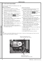
H
L
Maximum Rate Adjustment Screw
(Firstly remove plastic cap for access)
Minimum rate adjustment
9.
To ensure the boiler operates at minimum rate without
modulating, set the fan speeds to minimum.
10.
To set the fan speed to minimum. Press and hold in the
'mode' and '-' buttons simultaneously on the Master
Module. The display will show as the first digit
indicating the boiler is operating at minimum rate.
Repeat on the Slave Module.
11.
Connect a suitable flue analyser to the flue sampling point
of the Master Module - see Frame 12.
12.
Remove the protective cap and then using the offset
adjustment screw, adjust the valve on the master module
until the CO
2
value measures 9.5% ± 0.2 (nb. anti-
clockwise reduces CO
2
level). The offset adjustment is a
lot more sensitive than the throttle adjustment.
13.
Connect a suitable flue analyser to the flue sampling point
on the Slave Module (see Frame 12).
14.
Remove the protective cap and then using the offset
adjustment screw, adjust the valve on the Slave Module
until the CO
2
value measures 9.5% ± 0.2 (nb. anti-
clockwise reduces CO
2
level).
15.
Re-check the CO
2
level at maximum rate and repeat steps
3 to 15 if necessary.
16.
Press the '+' and '-' buttons simultaneously to return to
normal operating mode.
17.
Seal adjustment screw with tamper proof paint.
Note.
It is possible to switch off the CH/DHW systems if the mode and +/- buttons are not held simultaneously. Refer to Frame 30
under the heading CH/DHW Systems for guidance.
Offset Adjustment Screw
(Firstly remove plastic cap for access)
SER
VICING

