Section 4 - Installation
INST
ALLA
TION
31
Installation and Maintenance
4.1.6 Hydronic Connections
4.1.7 Antifreeze Protection
ᘐ
CAUTION: To prevent blockage, care should be
taken to prevent solids, metal fillings, sealing tape, and
any other contaminant from entering the heating circuit.
Before connection to the heating system, the pipework
should be thoroughly cleaned in accordance with
BS7593:2019 to remove any contaminant.
The installation of the hydronic pipework must comply with
local directives and guidelines.
To optimise performance, the length of pipes between the
Heat Pump and the indoor system must be kept as short as is
possible and the resistance of the circuit should be minimised
by using the fewest number of elbows and pipe fixtures.
Suitable seals (fibre gasket, O-rings) are to be used in
appropriate applications. Where thread sealant is required
use PTFE tape, or sealing pastes (synthetic, dependant on
application). Face seal connections are to be tightened with
15 Nm to 35 Nm.
Hydronic connections must be made by ≥ 28 mm diameter
COPPER pipe for the 8 & 10 kW models and ≥ 22 mm
diameter COPPER pipe for the 4 & 5 kW models. The
diameter of the pipe is to be calculated based on the flow
rate and length requirements of the hydronic system.
Consideration of the internal diameter of selected pipework
must be taken into account when calculating the system
resistance and water velocities at the specified design flow
rates.
The water velocity in the pipe should be kept within the design
limits of the material used to avoid erosion, corrosion, and
excessive noise generation.
ᘐ
CAUTION:
When connecting metal pipes of different
materials, be sure to insulate the connections to prevent
galvanic corrosion.
It must be made sure that there is no transfer of vibration to
the dwelling or heating system. To protect the heating system
from vibration, braided hoses must be installed between the
Heat Pump and rigid pipework to prevent vibration from being
transferred to the system.
Local to the Heat Pump there should be means of isolation
and drainage to allow for temporary decommissioning.
External pipework must be insulated with UV/moisture
resistant insulation and have a wall thickness of ≥ 19mm.
ᘐ
CAUTION: Where any circuit pipework is exposed
to ambient temperatures below < 5 °C, antifreeze
protection must be installed. Failure to install adequate
antifreeze protection methods may lead to damage to
the system. Damage to equipment which do not have
adequate antifreeze protection methods is not covered
by warranty
ᘐ
WARNING: Do not use mono ethylene glycol. Use
propylene glycol only.
When the Heat Pump is exposed to freezing temperatures,
the primary heating circuit must either be:
• Charged with a glycol water mixture (refer to 5.2.2 System
Water Treatment on page 45)
• Installed with antifreeze protection valves on both the inlet
and outlet of the Heat Pump
If antifreeze valves are installed, they are to be installed close
to the Heat Pump which will drain the hydronic circuit in the
event of the hydronic temperature dropping below 3 °C . The
valves must be installed in accordance with their installation
manual.
ᘐ
WARNING: Do not install antifreeze valves if the
system has been charged with glycol
Sufficient trace heating must be implemented to prevent
freezing and subsequent blocking of the condensate disposal
system.
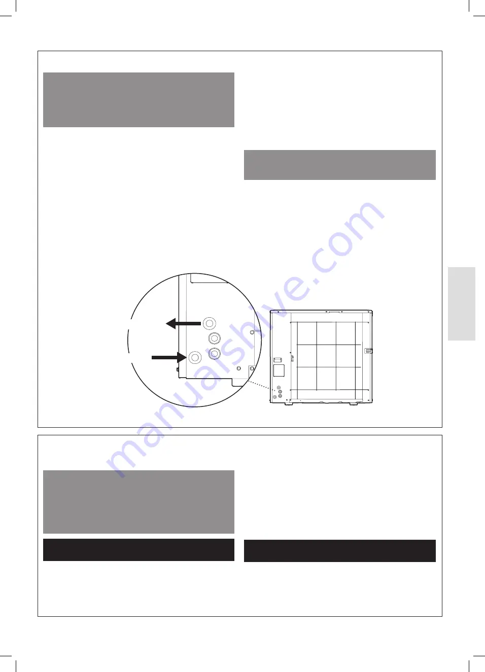
Primary Heating Flow
Primary Heating Return
Figure 32. Primary Heating Connections
Summary of Contents for Logic Air DHW IDEPLUHP180DUOPPSZ
Page 80: ...80 Installation and Maintenance Appendix 1 1 SYSTEM SCHEMATICS 1 1 1 Schematics Key Legend...
Page 82: ...Appendix 82 Installation and Maintenance 1 1 3 Logic Air Single Zone Pre Plumbed Cylinder...
Page 92: ...92 Installation and Maintenance Notes...


