49
Installation and Servicing
Section 3 - Servicing
SER
VICING
SCAN
for video
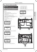
3.22 PRV REPLACEMENT
Refer to Section
3.2
Refer to Section
3.3
Refer to Section
3.3
Refer to Section
3.2
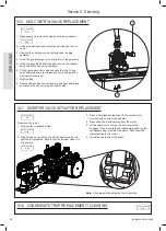
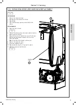
3.23 PUMP AUTOMATIC AIR VENT REPLACEMENT
1. Drain the boiler.
2. Remove the expansion vessel.
3. Firstly, increase access area by disconnecting the 22
mm pipe connection at top of pump manifold and bottom
of heat exchanger and remove pipe.
4. The automatic air vent head is retained in the pump body
with a bayonet connection. The air vent head and float
assembly is removed by turning the head anti-clockwise
(viewed from above) and pulling upwards.
5. Reassemble. Check the air vent head ‘O’ ring seal is
fitted.
6. Check that the air vent cap is loose.
7. Refill the boiler. Check for leaks around the new air vent
joint.
Refer to Section
3.31
Refer to Section
2.16
Refer to Section
2.18
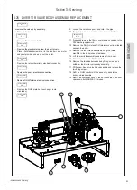
1. Drain the boiler.
2. Remove the trap and rubber pipe.
3. Pull out and remove the clip retaining the PRV.
4. Undo the discharge pipe compression coupling.
5. Lift out the PRV/pipe assembly.
6. Remove the pipe and transfer to the new PRV.
7. Reassemble ensuring the retaining clip is
correctly fitted.
8. Check the operation of the PRV by raising the
water pressure until the valve lifts. This should
occur within 0.3 bar of the preset lift pressure.
9. Check no escape of water occurs except at the
discharge point
10. Release water from the system until the
minimum system design pressure is reached;
1.0 bar if the system is to be pre-pressurised.
3


