background image

26

 Classic 

LXFF, FF 

Installation

SER

VICING

To ensure the continued safe and efficient operation of the
appliance, it is recommended that it is checked at regular
intervals and serviced as necessary. The frequency of
servicing will depend upon the installation condition and
usage, but should be carried out at least annually. It is the
law that any service work must be carried out by a CORGI
registered installer.

a.

Light the boiler and, using the flue sampling point
(provided on the top RH side of the back panel) carry out
a pre-service check, noting any operational faults.

b.

Clean the main burner.

c.

Clean the heat exchanger.

d.

Clean the main and pilot injectors.

e.

Remove any debris from inside the base of the casing.

f.

Check that the flue terminal is unobstructed and that the
flue system is sealed correctly.

g.

If the appliance has been installed in a compartment,
check that the ventilation areas are clear.

The servicing procedures are covered more fully in Frames
48 to 52 and must be carried out in sequence.

WARNING.


Disconnect the electrical supply and turn off gas

supply.

IMPORTANT.

 After completing the servicing or exchange of

components always test for gas soundness and carry out
functional checks as appropriate.

When work is complete the casing MUST be correctly
refitted, ensuring that a good seal is made.

T

he boiler must NOT be operated if the casing is not

fitted.

Note.

 In order to carry out either servicing or replacement of

components, the boiler casing must  be removed. Refer to
Frame 48.

3.

Pull the HT lead connection off the printed circuit board and
pull the lead upwards through the bottom panel grommet.

4.

Remove the 4 screws retaining the air box/pilot assembly to
the vertical manifold and carefully remove the assembly.

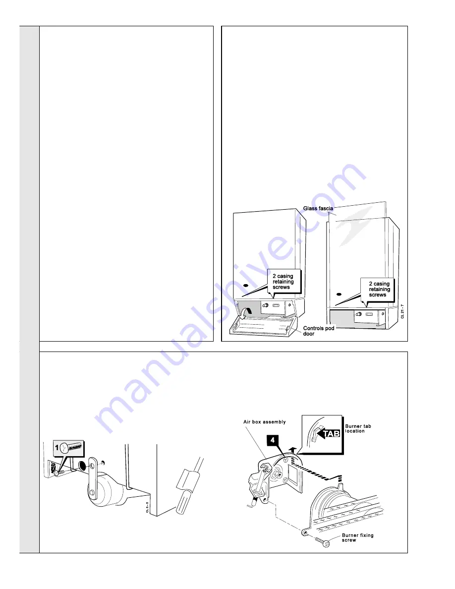
49 BURNER AND AIR BOX REMOVAL

1.

Remove the screw retaining the front burner support strap
to the combustion chamber. Remove the M5 pozi situated
at the LH bottom rear of the burner and pull the burner
downwards to disengage the retention tab. Remove the
burner to a safe place for inspection and cleaning.

2.

Remove the control box fixing screw. Pull the box forward
and downward to disengage.

Standard model

Deluxe model (LX)

1.

If the 

Classic Sealed System Unit

 is fitted (Standard boiler

only), lift off the casing.

2. Deluxe model (LX) 

-Lift the glass fascia and pull the sliding

catch out to retain the glass in the upper position.  Release
the 2 captive screws at the bottom of the casing. Swing the
bottom of the boiler casing out until the controls pod casing
has cleared the controls, then unhook the casing top from
the back panel.  Retain the casing in a safe place.

Standard model

 - Open the controls pod door and release

the 2 captive screws at the bottom of the casing.  Swing the
bottom of the boiler casing out until the controls pod casing
has cleared the controls, then unhook the casing top from
the pack panel. Retain the casing in a safe place.Where the
removal of the casing is impaired by a pelmet, the instruction
in Frame 2 (page 6) should should be followed.

3.

Isolate the gas supply at the service cock fitted to the boiler.

48 BOILER CASING REMOVAL

SERVICING

47 SCHEDULE

Summary of Contents for Classic FF230

Page 1: ......

Page 2: ...Classic LXFF FF Installation CAUTION To avoid the possibility of injury during the installation servicing or cleaning of this appliance care should be taken when handling edges of sheet steel componen...

Page 3: ...1 76 0 76 4 Boiler Size FF 230 FF 240 FF 250 FF 260 FF 270 FF 280 FF 2 100 Gas supply connection in BSP Rc 1 2 1 2 1 2 BSP Female Flow connection 22mm 28mm copper copper FEMALE Return connection 22mm...

Page 4: ...d appliance designed for connection via ducts to a horizontal or vertical terminal which admits fresh air to the burner and discharges the products of combustion to the outside through orifices which...

Page 5: ...ater central heating systems BS 5440 1 Flues for gas appliances of rated input not exceeding 60 kW BS 5440 2 Ventilation for gas appliances of rated input not exceeding 60 kW Health Safety Document No...

Page 6: ...e enough to accommodate the tool c If using the Complete Sealed System Unit then refer to the instructions packed with the unit for the necessary clearances Pelmet restrictions If the ability to fit o...

Page 7: ...l to obstructions and ventilation openings are specified in Table 3 4 Where the lowest part of the terminal is fitted less than 2m 6 6 above a balcony above ground or above a flat roof to which people...

Page 8: ...used for direct hot water supply For the types of system and correct piping procedure refer to Introduction and Frame 1 The central heating system should be in accordance with BS 6798 and in addition...

Page 9: ...circulator capable of providing an 11 C 20 F temperature differential e g Grunfos UPS 15 50 or equivalent The vertical distance between the pump and feed expansion cistern MUST comply with the pump m...

Page 10: ...ector hood assembly 2 Inter panel 3 Pumped return pipe 4 Rubber sealing grommets 5 Pumped flow pipe 6 Wall mounting plate 7 Sealing plates 3 off 9 Back panel 10 Controls support 11 Control box 12 Prog...

Page 11: ...wall plate 1 off z Terminal grille assy 1 off z Polyurethane foam seal 400 lg 1 off z No 8 x 8 lg Pozi pan hd screws 3 off 6 UNPACKING Pack A Contents z The complete boiler z Installation Servicing I...

Page 12: ...39 should be supported with the bracket provided If the stand off brackets have been used it is necessary in order to keep the flue aligned to use the spacer bracket with the support bracket It is MOS...

Page 13: ...shown 4 Mark onto the wall if required the following a The wall mounting plate screw positions choose one from each group Note Mark the centre of the flue hole as well as the circumference b The posi...

Page 14: ...t Ensure the boiler sealing ring is fully engaged Ensure the notch aligns with the groove on the outer flue duct This ensures correct alignment of the flue terminal 4 Stick the self adhesive foam stri...

Page 15: ...plate hooks as shown Do not use the burner controls for lifting 2 Fit the M8 screw washer and rectangular plate to retain the boiler Note Before fully tightening the M8 screw check the boiler alignme...

Page 16: ...making good the wall faces is not essential as seals are provided at both ends of the flue However both wall faces immediately around the cut hole should be flat make good if necessary For less accura...

Page 17: ...be is cut square mark the flue all the way round 4 Insert the cardboard duct ring for support and cut to length 5 Remove cardboard duct ring and remove any burrs 24 FITTING BOILER SEALING RING TO THE...

Page 18: ...s required then the downward routing pipe brackets and M8 spacer supplied in the Downward Piping Kit should be fitted to the wall mounting plate now 3 Fit the bottom 2 screws to secure the bracket s t...

Page 19: ...e fan 5 Pull the flue extension tube and engage onto the fan elbow and secure with the screw attached to the elbow Note The sealing ring studs will locate in the back panel one way only This will ensu...

Page 20: ...inal grille Boiler Extension tube Not for FF 2 100 model 33 FITTING THE KIT 1 Remove the cardboard support aid from the flue and place safely to one side 2 Fit the inner flue extension duct onto the i...

Page 21: ...wired into the mains lead in parallel with the control s to be overridden Refer to Frame 41 3 If a proprietary system is used follow the instructions supplied by the manufacturer 4 System designs fea...

Page 22: ...This is a fully controlled system set the boiler thermostat to maximum 4 Switchmaster Midi is similar in operation but the wiring differs slightly see the manufacturer s literature LEGEND b blue bk b...

Page 23: ...iler will be left off for more than a day or so then a frost thermostat should be wired into the system This is usually done at the programmer in which case the programme selector switches are set to...

Page 24: ...asing down and secure with the 2 captive screws To improve access to the gas valve remove the controls pod casing Release the controls pod front fixing screws 3 turns only Remove the pod by pulling it...

Page 25: ...them to the Householder 9 After installation commissioning and customer hand over instructionspleasecompletethe appliancelog book and leave this with the customer 10 Stress the importance of regular...

Page 26: ...iler casing must be removed Refer to Frame 48 3 Pull the HT lead connection off the printed circuit board and pull the lead upwards through the bottom panel grommet 4 Remove the 4 screws retaining the...

Page 27: ...nnect the fan leads 3a Rear flue Slacken the M4 screw securing the flue connector to the fan Disconnect the connector from the fan and slide into the flue 3b Side or top flue Slacken off two M4 screws...

Page 28: ...model illustrated For the deluxe model LX slide the glass fascia out before removing the sightglass assembly Refit the glass fascia after refitting the new sightglass assembly PILOT The pilot is fact...

Page 29: ...2 side retaining clips and remove the switch 12 Re assemble in reverse order 57 THERMOSTAT CONTROL THERMISTOR SENSOR LEAD and ON OFF SWITCH REPLACEMENT 58 PILOT BURNER REPLACEMENT 1 Refer to Frame 54...

Page 30: ...order 10 Replace the boiler casing 11 Check the gas valve operation 1 Refer to Frame 54 2 Remove the burner and air box assembly Refer to Frame 49 3 Remove the electrode retaining nut 4 Remove the pi...

Page 31: ...barbs on the PCB stand offs to release the PCB from the box 9 Fit the new PCB and re assemble in reverse order ensuring the correct orientation of the switch 10 Refit the boiler casing 11 Check the o...

Page 32: ...rews Retighten the screws 12 Replace the 2 rubber sealing grommets 13 Re assemble in reverse order 14 Remake all water connections ensuring that the compression fittings if used are correctly refitted...

Page 33: ...ssure switch Is the boiler casing correctly fitted Does the pilot light NO YES NO YES Does the spark stop after pilot is lit NO Is there a gas supply to the boiler Is the pilot injector blocked YES Re...

Page 34: ...at knob 1 079601 25 386 149 Automatic ignition printed circuit board PACTROL PCB 25 B 1 079716 27 385 861 Pressure switch HONEYWELL YAMATAKE C6065 A 1010 1 111379 28 E02 661 Fan assembly SIFAN No WFFB...

Page 35: ...d pilot assembly 13 Main burner 14 Main burner injector 69 BURNER ASSEMBLY Exploded View LEGEND Numbers up to 51 relate to the B G spares list 20 Control box 21 Thermostat potentiometer 24 Thermostat...

Page 36: ...36 Classic LXFF FF Installation 71 BOILER CASING ASSEMBLY SHORT LIST OF PARTS Deluxe model LX Standard model 72 SHORT PARTS LIST...

Page 37: ...Classic LXFF FF Installation 37...

Page 38: ...01482 492 251 Fax 01482 448 858 Registration No London 322 137 Registered Office National Avenue Kingston upon Hull HU5 4JN A subsidiary of Caradon p l c THIS SYMBOL IS YOUR ASSURANCE OF QUALITY These...

Page 39: ...l be giving away a free boiler for the five best ideas every year to be selected by our Technical Director Please complete this form using extra sheets if required and post it or fax it to us on 01482...

Page 40: ...to contact me Please arrange for me to join an Ideal factory tour Range guides required The Ideal Guide a specifier s and installer s introduction to the Ideal domestic boiler range The Ideal Househo...

Reviews: