Overview 2-3
Hardware
Se
tt
ings
Overview
This chapter provides jumper, header, and connector definitions and positions. Default settings
from the factory are marked with an asterisk (*).
Jumpers
In general, jumpers on the Endeavor Plus single board computer are used to select feature
options (Figure 2-1). Some jumpers are designed to be user-configurable, allowing for system
enhancement. The others are used for testing purposes only and should not be altered.
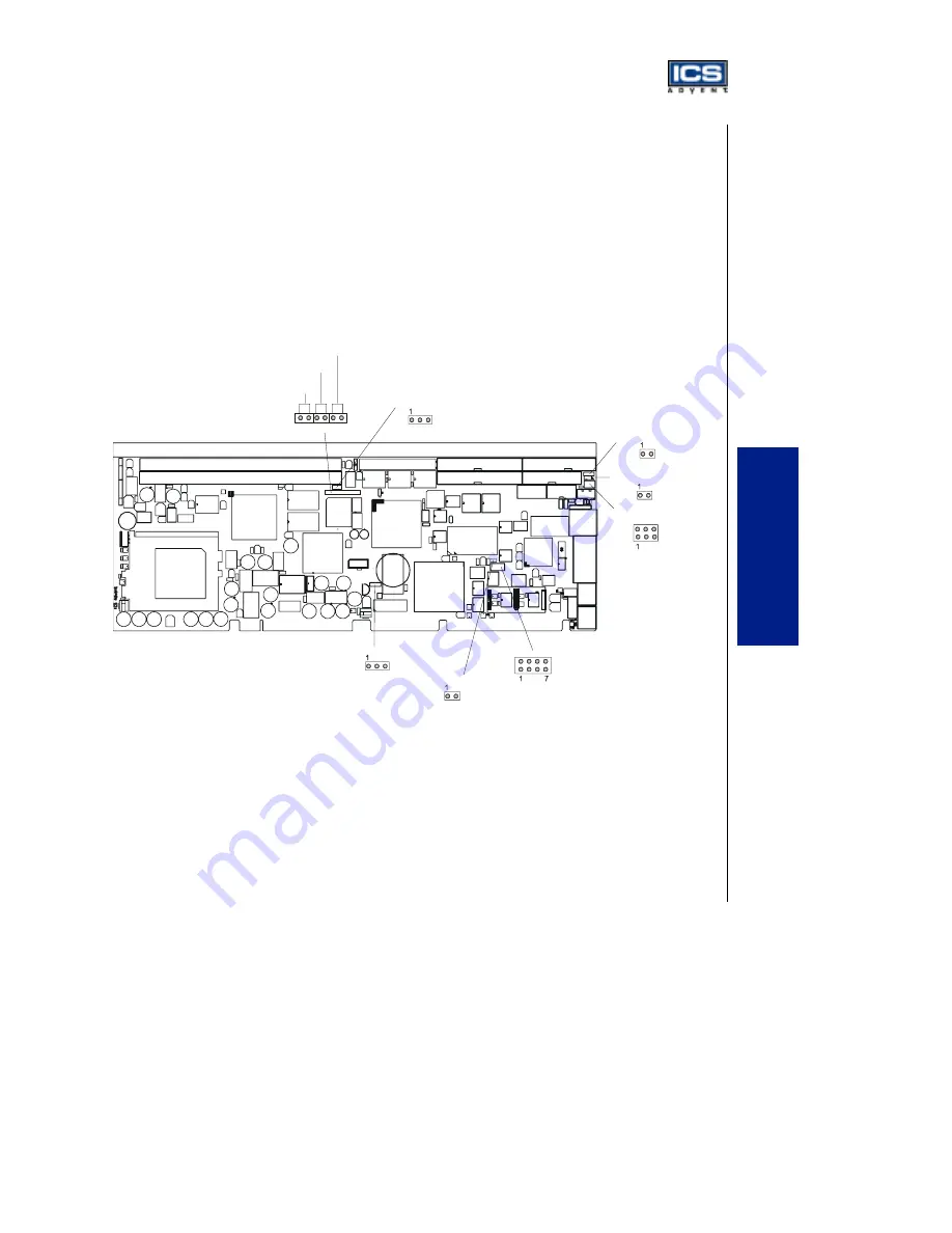
Figure 2-1. Endeavor Plus Jumper Locations
DIMM2
Socket 370
82810E
82801AA
DIMM1
PC87200
AIC-7892B
82559
W83627HF
2 3
Ethernet (JP15)
Watchdog Timer (JP16)
Disk-On-Chip (JP12)
2
2
8
2
2
2
5
CMOS Clear Function (JP1)
ATX Power Button (JP2)
AT/ATX Power Select (JP3)
6
1 2 1 2
1 2
Safe Mode (JP6)
FWH Write Protection (JP7)
SCSI Termination (JP8)
SCSI Enable/Disable (JP4)
2 3
3
4
3
4
5
6


