background image


 16


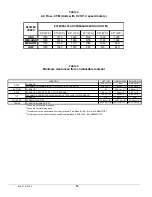
Table 3 

Air Flow - CFM (Units with 1/2 HP, 4 speed motors) 


Table 4 

Minimum clearances from combustible material 


0.2" (W.C.)

0.3" (W.C.)

0.4" (W.C.)

0.5"  (W.C.)

0.6"  (W.C.)

0.7"  (W.C.)

HIGH

1550

1510

1460

1400

1320

1220

MED-HIGH

1320

1280

1240

1200

1160

1020

MED-LOW

1180

1150

1110

1080

1040

940

LOW

1070

1040

1010

980

910

840

BLOWER

SPEED

EXTERNAL STATIC PRESSURE WITH AIR FILTER

UPFLOW

HORIZONTAL

DOWNFLOW

FURNACE 

1

2.54 cm (1")

N/A

5.08 cm (2" )

PLENUM AND WARM-AIR DUCT WITHIN 6 ft. OF FURNACE 

1

5.08 cm (2")

2.54 cm (1")

5.08 cm (2" )

BOTTOM

FURNACE 

2

Ø

2.54 cm (1")

3

5.08 cm (2")

4

BACK

FURNACE (OPPOSITE SIDE OF THE B URNER) 

1

7.62 cm (3")

7.62 cm (3")

7.62 cm (3" )

PLENUM OR HORIZONTAL WARM-AIR DUCT WITHIN 6 ft. OF FURNACE 

2

5.08 cm (2")

7.62 cm (3")

5.08 cm (2" )

FURNACE 

2

N/A

5.08 cm  (2")

N/A

FLUE PIPE

AROUND FLUE PIPE

22.86 cm (9" )

22.86 cm (9")

22.86 cm (9")

FRONT

FURNACE (BURNER S IDE) 

1

45.72 cm (18")

45.72 cm (18")

45.72 cm (18")

1  

These are horizontal dimensions 

2  

These are vertical dimen sions

3


This dimensi on can be  obtained  by  using Horizontal Flow  Base #  HFB-101 or  # K LASB0701DET

4


This dimension can  be obtained by using Downflow  Base #  DFB-103 or  # K LASB0901DET

LOCATIO N

SIDES

TOP

445 01 4101 00

Summary of Contents for OMF112K14A

Page 1: ...HE INFORMATION IN THIS MANUAL FOR THE INSTALLATION SERVICING OF THE FURNACE AND KEEP THE DOCUMENT NEAR THE UNIT FOR FUTURE REFERENCE HOMEOWNER PLEASE KEEP THIS MANUAL NEAR THE FURNACE FOR FUTURE REFER...

Page 2: ...LE SPEED MOTORS 9 2 13 INSTALLATION OF ACCESSORIES 9 3 OPERATION 10 3 1 START UP 10 3 2 OPERATING SEQUENCE OIL HEATING MODE 10 3 3 CHECKS AND ADJUSTMENTS 10 4 MAINTENANCE 12 4 1 CLEANING THE HEAT EXCH...

Page 3: ...on such as the model and serial numbers of the furnace WARNING Installations and repairs performed by unqualified persons can result in hazards to them and to others Installations must conform to loca...

Page 4: ...t designed for outdoor installation It must be installed in such a manner as to protect its electrical components from water Outdoor installation will lead to a hazardous electrical condition and to p...

Page 5: ...f bodily harm if ever an electrical problem develops A green ground screw is supplied with the control box for that purpose The appliance must be installed in accordance with the current ANSI NFPA 70...

Page 6: ...e burner for the first time adjust the air and turbulator settings to those listed in this manual Once the burner becomes operational final adjustments will be required Refer to section 3 of this manu...

Page 7: ...Test The purpose of the following test is to check that the electrical outlet on the furnace designated to the BVSO is functional 1 Start up the burner 2 Remove the three pole plug from the BVSO outle...

Page 8: ...istance 2 10 DUCTING WARNING Poisonous carbon monoxide gas hazard DO NOT draw return air from inside a closet or utility room Return air MUST be sealed to the furnace casing Failure to properly seal d...

Page 9: ...GPH OFF OFF A 0 68 ON OFF B 0 80 OFF ON C ALL ON ON D ALL 2 13 INSTALLATION OF ACCESSORIES WARNING Electrical shock hazard Turn OFF electrical power at the fuse box or service panel before making any...

Page 10: ...are appropriate and according to the specifications in this manual 8 The blower start stop delays are satisfactory 9 The thermostat of the room is in the heating mode and is set higher than the ambie...

Page 11: ...bove the burner is a measurement necessary to determine if there is a blockage in the heat exchanger or the flue pipe Refer to the Technical Specifications in this manual for overfire pressure values...

Page 12: ...combustion chamber should be inspected to determine if replacement is required 8 After the cleaning replace the heat exchanger baffles flue collar plate and oil burner 9 Readjust the burner for proper...

Page 13: ...ephone Day Night Dealer name and address START UP RESULTS Nozzle Pressure lb po 2 Burner adjustments Primary air Fine air Drawer Assembly CO2 Smoke scale Bacharach Gross stack temperature F Ambient te...

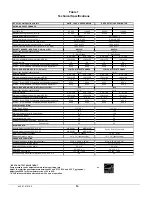
Page 14: ...n 85 2 85 0 85 2 85 0 RIELLO BURNER MODEL 40 BF5 Direct vent DV Burner tube insertion length inches Nozzle Delavan 0 60 70A 0 70 70A 0 60 70A 0 70 70A Minimum and Maximum pump pressure PSIG 130 to 160...

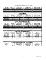
Page 15: ...me ShortRun On Delay CFM Level Time Off Delay CFM Level Time A 1 OFF 2 OFF 0 68 13 45 sec 19 60 sec 38 3 min B 1 ON 2 OFF 0 80 13 45 sec 19 30 sec 38 3 min C 1 OFF 2 ON All 13 45 sec 100 0 sec 100 2 m...

Page 16: ...ACE 1 5 08 cm 2 2 54 cm 1 5 08 cm 2 BOTTOM FURNACE 2 2 54 cm 1 3 5 08 cm 2 4 BACK FURNACE OPPOSITE SIDE OF THE BURNER 1 7 62 cm 3 7 62 cm 3 7 62 cm 3 PLENUM OR HORIZONTAL WARM AIR DUCT WITHIN 6 ft OF...

Page 17: ...17 Figure 5 Furnace dimensions 445 01 4101 00...

Page 18: ...18 Figure 6 Wiring Diagram 4 Speed Motor PSC 445 01 4101 00...

Page 19: ...19 Figure 7 Wiring Diagram Variable Speed Motor ECM 445 01 4101 00...

Page 20: ...20 PARTS LIST With 4 Speed motor PSC B50091B 445 01 4101 00...

Page 21: ...MBLY Blower motor and capacitor included 24 Z06G001 BLOCKED VENT SHUT OFF BVSO 225 25 B03118 01 ELECTRICAL KIT BVSO EXT 26 L07F003 ROCKER SWITCH DPST 27 L04I013 STRAIN RELIEF BUSHING 28 L04J001 CABLE...

Page 22: ...22 PARTS LIST With variable speed motor ECM B50092B 445 01 4101 00...

Page 23: ...EMBLY Blower motor and capacitor included 24 Z06G001 BLOCKED VENT SHUT OFF BVSO 225 25 B03118 01 ELECTRICAL KIT BVSO EXT 26 L04I013 STRAIN RELIEF BUSHING 27 L04J001 CABLE CLAMP 9 16 WHITE 28 B03640 WI...

Reviews: