
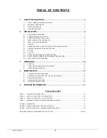


7
2.6.1 Masonry chimney
This furnace can be vented into an existing masonry chimney.
However, the unit must not be vented into a chimney into
which a solid fuel burning furnace is already being vented.
Before venting this furnace into a chimney, its condition must
be checked and repairs made, if necessary. Also, the chimney
lining and dimensions must conform to local and national
codes.
2.6.2 Factory Built Chimneys
Oil fired furnaces are approved for use with “L” type vents. The
unit may also be used with an approved chimney of proper
dimensions and temperature ratings as specified in the
installation code. Refer to chimney manufacturer’s instructions
for proper installation.
2.6.3 Draft Regulator
This unit may be installed with or without a draft regulator.
However, it is recommended that a draft regulator be installed
in cases where the draft is either high or variable due to
external conditions. Follow the instructions provided with the
regulator.
2.6.4 Side-wall Venting
The heating unit is approved for side-wall venting. This system
is comprised of a model VTK-098 / KLAVT0101DET side-wall
venter and a 4” insulated vent pipe, model IFV098 /
KLAFVxx01DET. Refer to the installation instructions provided
with the venting system.
2.7 BLOCKED
VENT
SHUT-OFF
DEVICE
(BVSO)
FOR
CHIMNEY
VENTING
CAUTION
It is imperative that this device be installed by a qualified service
technician.
A positive pressure venting system (Sealed Combustion System
or Direct Vent)
MUST NOT
use the BVSO. Follow the
instructions supplied with the venting system.
This device is designed to detect the insufficient evacuation of
combustion gases in the event of a vent blockage. In such a
case the thermal switch will shut down the oil burner. The
device will then need to be re-armed MANUALLY.
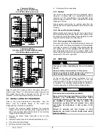
Refer to the detailed instructions and wiring diagrams supplied
with the BVSO for the installation and wiring procedures. The
length of wires supplied with the unit is such that the safety
device must be installed between the flue outlet of the
appliance and the draft regulator, as indicated in the
instructions.
It is also essential that the BVSO be maintained annually. For
more details refer to the instructions supplied with the device
itself, as well as Section 3. of this Manual.
2.7.1 BVSO Performance Test
The purpose of the following test is to check that the electrical
outlet on the furnace, designated to the BVSO, is functional.
1. Start up the burner;
2. Remove the three-pole plug from the BVSO outlet on
the furnace;
3. The burner must shut-off immediately, while the
blower continues to run to the end of the cool-down
cycle.
If the test is not in line with the above, call a QUALIFIED
SERVICE TECHNICIAN.
2.8 COMBUSTION
AIR
SUPPLY
AND
VENTILATION
WARNING
Poisonous carbon monoxide gas hazard.
Comply with NFPA 31 (U.S.) and CSA B139 (Canada)
standards for the installation of Oil Burning
Equipment and applicable provisions of local building
codes to provide combustion and ventilation air.
Failure to provide adequate combustion and
ventilation air can result in death, bodily injury and/or
property damage.
Oil furnaces must have an adequate supply of combustion
air. It is common practice to assume that older homes
have sufficient infiltration to accommodate the combustion
air requirement for the furnace. However, home
improvements such as new windows, doors, and weather
stripping have drastically reduced the volume of air
infiltration into the home.
Refer to oil furnace installation codes relative to
combustion and ventilation air requirements. Consult
Section 2.2 in this manual, specifically for units installed in
an enclosed space.
Home air exhausters are common. Bathroom and kitchen
fans, power vented clothes dryers and water heaters all
tend to create a negative pressure condition in the home.
Should this occur the chimney becomes less and less
effective and can easily downdraft. In certain cases,
mechanically supplied air, by way of a blower, interlocked
with the unit, is necessary. It is the installer’s responsibility
to check that.
2.8.1
Contaminated Combustion Air
Installations in certain areas or types of structures will
increase the exposure to chemicals or halogens that may
harm the furnace. These conditions will require that only
outside air be used for combustion.
The following areas or types of structures may contain or
be exposed to certain substances, potentially requiring
outside air for combustion:
a. Commercial
buildings;
b. Buildings with indoor pools;
c.
Furnaces installed near chemical storage areas.
Exposure to the following substances:
a. Permanent wave chemicals for hair;
b. Chlorinated waxes and cleaners;
c.
Chlorine based swimming pool chemicals;
d. Water softening chemicals;
e. De-icing salts or chemicals;
f. Carbon
tetrachloride;
445 01 4101 00
Summary of Contents for OMF112K14A
Page 17: ...17 Figure 5 Furnace dimensions 445 01 4101 00...
Page 18: ...18 Figure 6 Wiring Diagram 4 Speed Motor PSC 445 01 4101 00...
Page 19: ...19 Figure 7 Wiring Diagram Variable Speed Motor ECM 445 01 4101 00...
Page 20: ...20 PARTS LIST With 4 Speed motor PSC B50091B 445 01 4101 00...
Page 22: ...22 PARTS LIST With variable speed motor ECM B50092B 445 01 4101 00...