background image

54

13

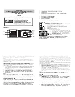
HM-127 REMOTE-CONTROL MICROPHONE

Starting a scan

q

Push [CH/WX•U/I/C] several times
while pushing [H/L] to select the
channel group (USA, INT, CAN), if
desired.

• When the weather alert function is in

use, select the desired weather channel
with [CH/WX] and [

Y

]/[

Z

].

w

Push [SCN] to start priority or normal
scan.

• “SCAN” appears during normal scan.
• The priority channel readout indicates

“16”, and “P” and “SCAN” indicators ap-
pear during priority scan.

• When a signal is received, scan pauses

until the signal disappears or resumes
after pausing 5 sec. according to set
mode setting (Channel 16 is still moni-
tored during priority scan).

• Push [

Y

]/[

Z

] to check the scanning tag

channels, to change the scanning direc-
tion or resume the scan manually.

e

To stop the scan, push [SCN].

• “SCAN” disappears.
• Pushing [PTT], [16•9] or [CH/WX] also

stops the scan.

Setting tag
channels

q

Push [CH/WX•U/I/C] several times
while pushing [H/L] to select the
channel group (USA, INT, CAN), if
desired.

w

Push [

Y

]/[

Z

] to select the desired

channel to set as a tag channel.

e

Push [SCN•TAG] for 1 sec. to set the
displayed channel as a tag channel.

• “

” appears.

r

To cancel the tag channel setting,
push [SCN•TAG] for 1 sec.

• “

” disappears.

• Clearing all tag channels in the

selected channel group

Push [SCN•TAG] while pushing [H/L]
for 3 sec. (until long beep changes to
2 short beeps).

Dualwatch/Tri-
watch operation

q

Push [

Y

]/[

Z

] to select the desired

channel.

• Push [CH/WX•U/I/C] several times while

pushing [H/L] to select the channel
group (USA, INT, CAN), if desired.

w

Push [CH/WX•DW] for 1 sec. to start
dualwatch or tri-watch.

• “DUAL” appears during dualwatch; “TRI”

appears during tri-watch.

• Beep tone sounds when a signal is re-

ceived on channel 16.

• Tri-watch becomes dualwatch when re-

ceiving a signal on the call channel.

e

To cancel dualwatch/tri-watch, push
[CH/WX•DW] again.

Summary of Contents for IC-M502

Page 1: ...ce complies with Part 15 of the FCC rules Operation is sub ject to the following two conditions 1 This device may not cause harmful interference and 2 this device must accept any interference received including interference that may cause undesired operation ...

Page 2: ...el 16 is automatically selected 3 Push and hold PTT then transmit the appropriate information as at left USING CHANNEL 16 DISTRESS CALL PROCEDURE 1 MAYDAY MAYDAY MAYDAY 2 THIS IS name of vessel 3 Your call sign or other indication of the vessel AND 9 digit DSC ID if you have one 4 LOCATED AT your position 5 The kind of the distress and assistance required 6 Any other information which might facili...

Page 3: ...eceive messages 28 7 INTERCOM OPERATION 29 Intercom operation 29 8 SET MODE 30 33 Set mode programming 30 Set mode items 31 9 CONNECTIONS AND MAINTENANCE 34 39 Supplied accessories 34 Antenna 34 Fuse replacement 34 Cleaning 34 Connections 35 Mounting the transceiver 36 Optional unit installation 38 Dimensions 39 10 TROUBLESHOOTING 40 11 CHANNEL LIST 41 12 SPECIFICATIONS AND OPTIONS 42 43 Specifica...

Page 4: ...e the transceiver in areas with temper atures below 4 F 20 C or above 140 F 60 C or in areas subject to direct sunlight such as the dashboard AVOID the use of chemical agents such as benzine or al cohol when cleaning as they may damage the transceiver surfaces BE CAREFUL The transceiver rear panel will become hot when operating continuously for long periods Place the transceiver in a secure place ...

Page 5: ...io purposes 2 OPERATOR S LICENSE A Restricted Radiotelephone Operator Permit is the license most often held by small vessel radio operators when a radio is not required for safety purposes The Restricted Radiotelephone Operator Permit must be posted or kept with the operator Only a licensed radio opera tor may operate a transceiver However non licensed individuals may talk over a transceiver if a ...

Page 6: ...oggle the transceiver power ON and OFF w VOLUME CONTROL VOL Adjusts the audio level p 8 e SQUELCH CONTROL SQL Sets the squelch threshold level p 8 r TRANSMIT POWER SWITCH HI LO Toggles high and low power when pushed p 8 Some channels are set to low power only While pushing this switch other switches perform sec ondary functions t CHANNEL SELECTOR CHANNEL Rotate CHANNEL to select the operating chan...

Page 7: ... dition when call channel is selected p 9 While pushing HI LO enters memory name program ming condition p 9 Enters set mode when pushed while turning power ON p 30 i DISTRESS SWITCH DISTRESS Transmits distress call when pushed for 5 sec p 16 o CHANNEL DUALWATCH TRI WATCH SWITCH CH WX DW U I C Selects and toggles the regular channels and weather channel when pushed momentarily pgs 6 7 While pushing...

Page 8: ...pears when an optional voice scrambler is activated y DUPLEX INDICATOR p 6 Appears when a duplex channel is selected u CHANNEL NUMBER READOUT Indicates the selected operating channel number A appears when a simplex channel is selected p 6 In set mode indicates the selected condition p 30 i CHANNEL GROUP INDICATOR p 6 Indicates whether an International INT U S A USA Canadian CANADA or weather WX ch...

Page 9: ...DOWN SWITCHES Y Y Z Z Push either switch to change the operating memory chan nel set mode contents etc p 8 e TRANSMIT POWER SWITCH HI LO Same as the HI LO switch on the front panel p 8 While pushing HI LO on the supplied microphone turn power ON to toggle the lock function ON and OFF p 7 Speaker Microphone w q e ...

Page 10: ... recall Push 16 9 for 1 sec to select the call channel of the se lected channel group CALL and call channel number appear Each channel group may have an independent call channel after changing a call channel Push CH WX to return to the condition before selecting call channel or rotate CHANNEL to select operating channel U S A Canadian and international channels There are 57 U S A 61 Canadian and 5...

Page 11: ...cted WX ALT appears when the weather alert function is in use p 31 w Rotate the channel selector to select a channel Channels are memorized separately for each channel group Microphone lock function The microphone lock function electrically locks the Y Z and HI LO switches on the supplied microphone This pre vents accidental channel changes and accidental function ac cess While pushing HI LO on th...

Page 12: ...essary LOCAL appears when the receive attenuator is in use y Push HI LO to select the output power if necessary 25W or 1W appears when high or low power is selected re spectively Choose low power to conserve power choose high power for longer distance communications Some channels are for low power only u Push and hold PTT to transmit then speak into the mi crophone TX appears Channel 70 cannot be ...

Page 13: ... selector to select the desired chan nel t Push 16 9 to program the displayed channel as the call channel Push CH WX to cancel The channel number stops flashing Channel names Memory channels can be tagged with alphanumeric names of up to 10 characters each Capital letters small letters numerals some symbols and spaces can be used q Select the desired memory channel Cancel dual watch tri watch or s...

Page 14: ... repeat step w SC disappears Programming scrambler codes There are 128 or 32 codes 0 to 127 or 1 to 32 available for programming when the optional UT 98 or UT 112 is installed In order to understand one another all transceivers in your group must have the same scramble code This function may not be available depending on dealer setting q Turn power OFF w While pushing 16 9 turn power ON to enter s...

Page 15: ... C again Example Operating tri watch on INT channel 25 DUALWATCH TRI WATCH SIMULATION If a signal is received on channel 16 dualwatch tri watch pauses on channel 16 until the signal disappears If a signal is received on the call channel during tri watch tri watch becomes dualwatch until the signal disappears To transmit on the selected channel during dualwatch tri watch push and hold PTT Dualwatch...

Page 16: ...or normal scan in set mode p 31 NORMAL SCAN Normal scan like priority scan searches through all tag channels in sequence However unlike priority scan chan nel 16 is not checked unless channel 16 is set as a tag channel 5 SCAN OPERATIONS PRIORITY SCAN Priority scan searches through all tag channels in se quence while monitoring channel 16 When a signal is de tected on channel 16 scan pauses until t...

Page 17: ...ls in the selected channel group While pushing HI LO push SCAN TAG for 3 sec to clear all tag channels in the channel group Starting a scan Set scan type priority or normal scan and scan resume timer in advance using set mode p 31 q Set tag channels as described at left w Make sure the squelch is closed to start a scan e While pushing HI LO push CH WX DW U I C one or more times to select the desir...

Page 18: ...ut 9 digit code u Push DSC ENT to input and set the code The previously selected channel appears Position and time programming A distress call should include the ship s position and time If no GPS is connected your position and UTC Universal Time Coordinated time should be input They are included auto matically when a GPS receiver NMEA0183 ver 2 0 is con nected This function is not available when ...

Page 19: ...dication When an optional GPS receiver NMEA0183 ver 2 0 is con nected the transceiver can display the current position and time When no GPS receiver is connected the transceiver displays the manually entered position and time A GPS receiver appropriate for the IC M502 is not supplied from Icom An NMEA0183 ver 2 0 is required for position in dication Ask your dealer about the GPS receiver Push DSC ...

Page 20: ...tting the call the transceiver waits for an ac knowledgment call on Ch70 The distress call is automatically transmitted every 3 5 to 4 5 minutes r When receiving the acknowledgment reply to the con nected station via the microphone Distress alert contains default Kinds of distress Undesignated distress Position data GPS or manual input position data held for 23 5 hrs or until the power is turned O...

Page 21: ...n be set in advance p 22 t Push DSC ENT to transmit the individual call Channel 70 is selected and the individual call is transmitted to the selected station If channel 70 is busy the transceiver standbys until the channel becomes clear Routine category only is available y Standby on channel 70 until an acknowledgement is re ceived u When the acknowledgement is received the display changes to the ...

Page 22: ... code then push DSC ENT t Rotate the channel selector to select an acknowledgement Able or Unable then push DSC ENT y If you select Unable select the reason by rotating the channel selector then push DSC ENT No reason given Congestion Busy Queue indication Barred Station barred No operator No Equip Equipment disable No channel Unable channel and No mode Unable mode are available u Push DSC ENT to ...

Page 23: ...h DSC ENT to select the DSC menu e Rotate the channel selector to select All ships and push DSC ENT r Push DSC ENT to transmit the all ships call Channel 70 is selected and the all ships call is transmitted Routine category only is available t The all ships call has been transmitted y Push PTT or rotate the channel selector to exit the condi tion All ships Completed To call To cancel other DSC ENT...

Page 24: ... the position request call is transmit ted t The position request call has been transmitted y Push PTT or rotate the channel selector to exit the condi tion Transmitting position reply call Transmit a position reply call when a position request call is received q When a position request call is received the function dis play shows as follows w Push DSC ENT to reply the position request call push H...

Page 25: ...ition information appears Set the current position then push DSC ENT Rotate the channel selector to select the character Push CH WX to advance the cursor Push SCAN to move the cursor backward Push HI LO to clear the position data t The time information appears Set the current time then push DSC ENT Rotate the channel selector to select the numeral Push CH WX to advance the cursor Push SCAN to move...

Page 26: ...character Push CH WX to advance the cursor Push SCAN to move the cursor backward Push HI LO to cancel and exit the condition t Push DSC ENT to program and to exit the condition Deleting address ID q Push DSC ENT to select the DSC menu w Rotate the channel selector to select Set up and push DSC ENT e Rotate the channel selector to select Delete ID then push DSC ENT When no address ID is programmed ...

Page 27: ...op the alarm Received Distress appears in the display then channel 16 is automatically selected Continue monitoring channel 16 as a coast station may re quire assistance Receiving a distress acknowledgement While monitoring channel 70 and a distress acknowledge ment to other ship is received Emergency alarm sounds for 2 minutes Push any switch to stop the alarm Received Distress ACK appears in the...

Page 28: ... channel 70 and an all ships call is received Emergency alarm sounds when the category is Distress or Urgency 3 beeps sound for other categories All ships Distress All ships Safety or All ships Urgency appears in the display then the channel specified by the calling station is automatically selected for voice communi cation Monitor the selected channel for an announcement from the calling vessel R...

Page 29: ... your position Receiving a position reply call While monitoring channel 70 and a position reply call for the area you are in is received Received POS appears in the display When no GPS receiver is connected or if there is a prob lem with the connected receiver all geographical area calls are received regardless of your position Receiving a position request call While monitoring channel 70 and a po...

Page 30: ...t time then push DSC ENT r Set the offset time from the UTC Universal Time Coordi nated time then push DSC ENT Rotate the channel selector to select the number or Push CH WX to advance the cursor Push SCAN to move the cursor backward Push HI LO to cancel and exit the condition t Push DSC ENT to program and to exit the condition Offset time 00 00 Offset time 12 00 No offset time default 12 hours Se...

Page 31: ... the DSC menu w Rotate the channel selector to select Set up and push DSC ENT e Rotate the channel selector to select MMSI check then push DSC ENT r Check the 9 digit MMSI DSC self ID code t Push DSC ENT to exit the condition MMSI check 123456789 Set up Offset time Delete ID MMSI check Sel item RCV calls DTRS set Set up ...

Page 32: ... Rotate the channel selector to select the desired message then push DSC ENT t Rotate the channel selector to scroll the message The stored message has several information and depends on the distress call types y Push DSC ENT to exit the condition or push HI LO to clear the displayed messages To clear this data No DSC ENT Yes H L Sel DTRS MSG Icom2 Smith John Distress Smith Explosion UTC 12 34 LAT...

Page 33: ...ay respectively To adjust the IC M502 s speaker output level rotate VOL To adjust the HM 127 s speaker output level push Y Z after pushing VOL r After releasing the PTT switch you can hear the response through the speaker t To return to normal operation push LO DX IC SCR mo mentarily Other switches also turn the function OFF however the corre sponding function is then activated e g pushing 16 9 se...

Page 34: ...lwatch tri watch selection DSC watch transceiver s beep tone internal speaker transceiver or HM 127 LCD contrast transceiver or HM 127 RF atten uation level scrambler code and scrambler type Available functions may differ depending on dealer set ting The optional HM 127 has it s own settings for the beep tone and LCD contrast q Turn power OFF w While pushing 16 9 turn power ON to enter set mode e ...

Page 35: ...dcast station transmits a weather alert tone be fore important weather information When the weather alert function is turned ON the transceiver detects the alert then flashes the WX ALT indicator until the transceiver is oper ated The previously selected used weather channel is checked any time during standby or while scanning WX ALT appears instead of WEATHER indication when the func tion is set ...

Page 36: ...beep tones OFF or you can have confirmation beeps sound at the push of a switch by turning beep tones ON The optional HM 127 has it s own setting for the beep tone Internal speaker When an optional external speaker is connected and the transceiver s internal speaker is not required the speakers on the transceiver and microphone can be deactivated SP OFF appears on the function display when the int...

Page 37: ...de can be set depending on dealer setting When the UT 98 or UT 112 is installed 128 or 32 codes 0 to 127 or 1 to 32 can be selected respectively Scrambler type When an optional scrambler unit is connected the scrambler type can be selected in set mode depending on dealer set ting Set mode Scrambler type UT 98 scrambler unit UT 112 scrambler unit Set mode Scrambler code Scrambler code 0 UT 98 defau...

Page 38: ...antenna Ask your dealer about antennas and the best places to mount them Fuse replacement One fuse is installed in the supplied DC power cable If a fuse blows or the transceiver stops functioning track down the source of the problem if possible and replace the damaged fuse with a new rated one Cleaning If the transceiver becomes dusty or dirty wipe it clean with a soft dry cloth AVOID the use of s...

Page 39: ...receiver to input the position data and time data A GPS receiver appropriate for the IC M502 is not supplied from Icom An NMEA0183 ver 2 0 is required for position or time indi cation etc Ask your dealer about the GPS receiver t EXTERNAL SPEAKER JACK Connects to an external speaker See Options on p 43 for available external speakers MICROPHONE HANGER Rest the supplied microphone on the hanger when...

Page 40: ...ed screws M5 20 to a surface which is more than 10 mm thick and can support more than 5 kg Mount the transceiver so that the face of the transceiver is at 90 to your line of sight when operating it CAUTION KEEP the transceiver and microphone at least 1 meter away from your vessel s magnetic navigation compass NOTE Check the installation angle the function display may not be easy to read at some an...

Page 41: ...ount the controller w Slide the transceiver through the hole as shown below e Attach the 2 supplied bolts M5 8 mm on either side of the IC M502 r Attach the clamps on either side of the IC M502 Make sure that the clamps align parallel to the IC M502 s body t Tighten the end bolts on the clamps rotate clockwise so that the clamps press firmly against the inside of the in strument control panel y Ti...

Page 42: ...d or equip ment damage Follow the case opening procedure shown here when you want to install an optional unit etc q Remove the 6 screws as shown below and open the trans ceiver w Remove the 4 screws from the shielding plate then lift up the shielding plate e Plug an optional unit to J6 on the MAIN unit as shown below r Return the shielding plate and assemble the units to their original positions O...

Page 43: ...39 9 CONNECTIONS AND MAINTENANCE Dimensions 145 0 5 23 32 165 0 6 1 2 31 4 1 1 4 53 0 2 3 32 Unit mm inch 110 0 4 11 32 109 4 4 5 16 ...

Page 44: ...ow power or re ceive only The output power is set to low Change channels Push HI LO to select high power pgs 6 41 p 8 Scan does not start TAG channel is not programmed Set the desired channels as TAG chan nels p 13 No beep sounds Beep tone is turned OFF The squelch is open Turn the beep tone ON in set mode Set squelch to the threshold point p 32 p 8 Receive signal cannot be understood Optional voi...

Page 45: ...66A Frequency MHz 66A USA CAN Transmit Receive 64A 64A 156 225 156 225 65A 65A 156 275 156 275 156 325 160 925 67 67 156 375 156 375 68 68 156 425 156 425 69 69 156 475 156 475 70 70 156 525 156 525 71 71 156 575 156 575 72 72 156 625 156 625 73 73 156 675 156 675 74 74 156 725 156 725 77 77 156 875 156 875 156 925 161 525 78A 78A 156 925 156 925 156 975 161 575 79A 79A 156 975 156 975 157 025 161...

Page 46: ...ht 1130 g 2 lb 8 oz Transmitter Output power 25 W and 1 W Modulation system Variable reactance phase modulation Max frequency deviation 5 0 kHz Spurious emissions 70 dB Receiver Receive system Double conversion superheterodyne Sensitivity 12 dB SINAD Less than 0 25 µV typical Squelch sensitivity Less than 0 3 µV Intermodulation rejection ratio More than 80 dB typical Spurious response More than 80...

Page 47: ...10 33 UT 112 VOICE SCRAMBLER UNIT Ensures private communications 128 or 32 codes are avail able Not available in some countries HM 127 REMOTE CONTROL MICROPHONE p 44 External microphone type controller Provides optional inter com operation 6 m 20 feet microphone cable and mount ing base included Black and white colors are available OPC 999 MICROPHONE EXTENSION CABLE 6 m 20 feet microphone extensio...

Page 48: ...audio level or noise squelch level after VOL or SQL is pushed respectively pgs 8 51 In set mode changes setting of the selected item pgs 9 55 Checks tag channels or changes scanning direction dur ing scan pgs 8 54 r CHANNEL 16 CALL CHANNEL SWITCH 16 9 Selects channel 16 when pushed pgs 6 50 Selects call channel when pushed for 1 sec pgs 6 50 CALL appears when call channel is selected Push for 3 se...

Page 49: ...H L push SQL MONI L to toggle the microphone key lock function ON or OFF p 52 T appears while key lock function is in use PWR PTT VOL SQL and H L still function when the microphone key lock function is turned ON Advance the cursor while in memory name program ming condition pgs 9 56 i VOLUME DIMMER SWITCH VOL DIM Y Z adjusts the audio level after pushing VOL Push VOL DIM for 1 sec to adjust the br...

Page 50: ...ed t SQUELCH INDICATOR p 51 Appears while noise squelch level is adjusted y CHANNEL NAME INDICATOR Channel comment appears and scrolls if programmed pgs 9 56 In set mode indicates or scrolls the selected set mode item pgs 30 55 u ATTENUATOR INDICATOR pgs 8 51 Appears when the RF attenuator is in use i SCRAMBLER INDICATOR pgs 10 53 Appears when an optional voice scrambler is activated o SCAN INDICA...

Page 51: ... is selected 4 CALL CHANNEL INDICATOR pgs 6 50 Appears when the call channel is selected 5 DUPLEX INDICATOR pgs 6 50 Appears when a duplex channel is selected 6 TAG CHANNEL INDICATOR pgs 13 54 Appears when a tag channel is selected 7 BUSY INDICATOR pgs 8 51 52 Appears when receiving a signal or when the squelch opens 8 TRANSMIT INDICATOR pgs 8 51 Appears while transmitting HM 127 supplied accessor...

Page 52: ... ft Connecting between transceiver and the connection cable is available and up to 2 OPC 999 can be added q Insert the supplied cable into the external microphone jack and tighten the cable nut as shown below w To use the supplied cable as a wall socket follow the fol lowing steps e Using the mounting base carefully mark off the 2 spots where the cable and screws will be fastened r Drill holes at ...

Page 53: ...49 13 HM 127 REMOTE CONTROL MICROPHONE 50 d mm 1 31 32 23 d mm 29 32 24 to 27 d mm 15 16 to 1 1 16 5 mm 3 16 Gasket Mounting base Cap Nut 2 mm 3 32 ...

Page 54: ...rating channel Weather channels q Push CH WX once or twice to select weather channel group w Push Y or Z to select weather channel e Push CH WX to return to the condition before selecting the weather channel group U S A International and Canadian channels q Push CH WX to select regular channel Push CH WX again if weather channel appears w Push CH WX U I C while pushing H L to select chan nel group...

Page 55: ...mmunications Some channels are low power only t Push and hold PTT to transmit then speak into the mi crophone appears Channel 70 cannot be used for transmission for GMDSS use Simplex channels 3 21 23 61 64 81 82 and 83 CAN NOT be lawfully used by the general public in U S A wa ters y Release PTT to receive IMPORTANT To maximize the readability of your trans mitted signal voice pause a few sec afte...

Page 56: ... for better visibility under low light conditions And the backlighting con dition can be adjusted independently from the transceiver q Push VOL DIM for 1 sec to enter backlight adjusting mode with number of backlight level appears in the channel name indicator w Push Y Z to adjust the backlight level The backlight level is adjustable between 0 lights OFF and 7 brightest For your reference Pushing ...

Page 57: ...s the call channel The call channel number and channel group stop flashing Optional voice scrambler operation Activating the scrambler q Select an operating channel except channel 16 or weather channels w Push LO DX IC SCR while pushing H L to turn the voice scrambler function ON SCRM appears e To turn the scrambler func tion OFF repeat step w SCRM disappears Programming scramble codes There are 1...

Page 58: ...or CH WX also stops the scan Setting tag channels q Push CH WX U I C several times while pushing H L to select the channel group USA INT CAN if desired w Push Y Z to select the desired channel to set as a tag channel e Push SCN TAG for 1 sec to set the displayed channel as a tag channel appears r To cancel the tag channel setting push SCN TAG for 1 sec disappears Clearing all tag channels in the s...

Page 59: ...ontrast micro phone In this section instructions are for the microphone s own func tions only Refer pgs 30 33 for the setting of the other func tions Some functions may not be selected from the micro phone Entering set mode q Turn power OFF w While pushing 16 9 turn power ON After beep emission a set mode item in the channel name indi cator and condition in the channel number readout is displayed ...

Page 60: ...urned ON and the intercom mode is selected Intercom beep function Push LO DX IC for more than 1 sec Emits intercom beep while holding Channel names q Push Y Z to select a channel to program Push CH WX U I C several times while pushing H L to select the channel group USA INT CAN if desired w While pushing H L push 16 9 The 1st character of the currently programmed comment flashes e Push Y Z to sele...

Page 61: ...TEMPLATE 149 57 8 92 3 5 8 4 R11 Unit mm inch 24 to 27 d mm 15 16 to 11 16 2 mm 3 32 MB 75 HM 127 Cut here ...

Page 62: ...Count on us 1 1 32 Kamiminami Hirano ku Osaka 547 0003 Japan A 5663H 1EX w Printed in Japan 2000 Icom Inc ...

Reviews: