29
PREP
ARING THE
APPLIANCE
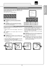
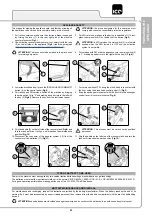
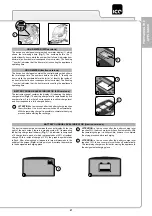
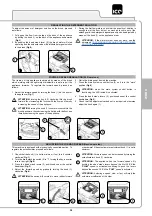
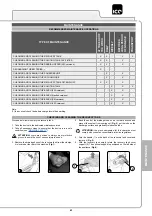
ASSEMBLING THE BRUSH HEAD SPLASH GUARD (SCRUB 55-65)
For packaging reasons, the brush head splash guard is supplied
disassembled from the device, and must be assembled on the brush
head unit as follows:
1. Take all necessary steps to ensure that the device is in a safe
’”).
ATTENTION:
these operations must be carried out using
protective gloves to avoid any possible contact with the edges
or tips of metal objects.
2. Position yourself at the front of the appliance.
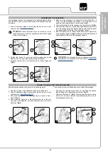
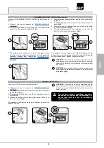
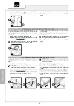
3. Insert the pins (1) present on the left splash guard (2) (
Fig.1
) into
the holes (3) present in the brush head body (4) (
Fig.2
).
4. Repeat the same operation for the right splash guard also.
BRUSH ASSEMBLY (SCRUB 55-65 with PM)
For packaging reasons, the brush is supplied disassembled from the
device. To assemble it on the brush head unit, proceed as follows:
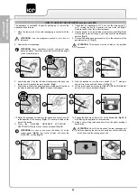
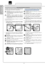
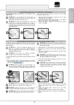
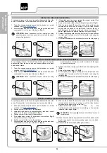
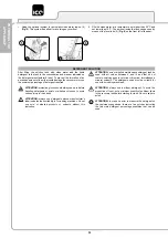
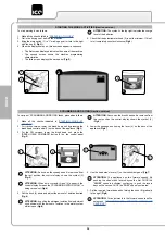
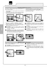
1. Check that the electronic brake is engaged, turn the lever (1) in
the rear right part of the machine anti-clockwise (
Fig.1
).
2. Check that the recovery tank is empty, if not, empty it with the tube
(2) on the left side of the appliance (
Fig.2
) (read the paragraph
CHECKING AND CLEANING THE RECOVERY TANK
”).
ATTENTION:
The tanks should be emptied in the place used
for draining dirty water.
ATTENTION:
the place designated for this operation must
comply with current environmental protection regulations.
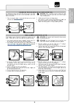
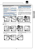
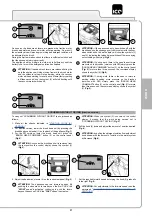
3.
Start the appliance, turn the main switch (3) to "I", making a
quarter turn to the right with the key (4)
Fig.3)
).
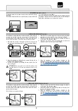
4. Lower the brush head unit, press the “BRUSH HEAD COMMAND”
button (5) on the control panel (
Fig.4
).
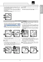
5.
As soon as the brush head is in contact with the floor, turn off
the appliance, turn the main switch (3) to "0", turning the key
(4) a quarter turn to the left (
Fig.5
). Remove the key from the
instrument panel.
6. Position yourself at the front of the appliance.
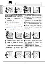
7. Remove the splash guard carters (6), remove them (
Fig.6
) and
lay them gently on the ground.
8. Position yourself at the rear of the appliance.
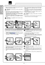
9. Insert the key (4) into the main switch (3).
10.
Start the appliance, turn the main switch (3) to "I", making a
quarter turn to the right with the key (4)
Fig.3)
).
11. Lift the brush head unit, press the “BRUSH HEAD COMMAND”
button (5) on the control panel (
Fig.4
).
12.
Turn off the appliance, turning the main machine switch (3) to "0",
turning the key (4) a quarter turn to the left (
Fig.5
). Remove the
key from the instrument panel.
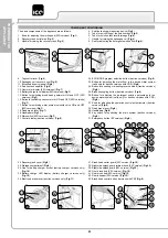
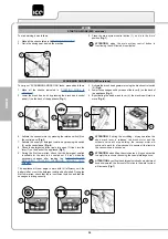
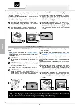
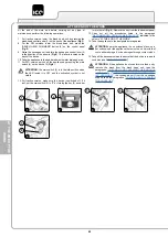
13. Grip the handle (7) on the left side of the recovery tank (
Fig.7
) and
turn the tank as far as it will go, until it reaches the maintenance
position (
Fig.8
).
1
4
2
3
2
1
1
2
1
2
4
3
3
5
4
4
3
6
5
6
7
8
7

