ELEVATION SERIES CIM CUBER
FAN MOTOR
51
Fan Motor
Operation
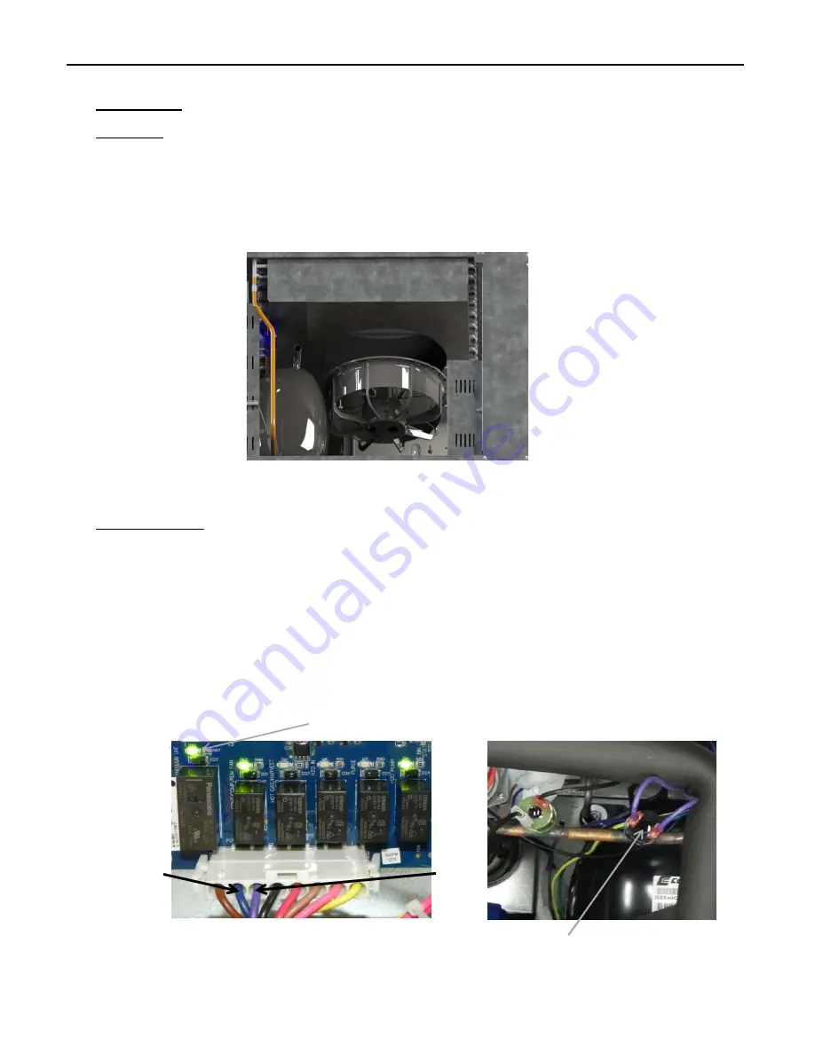
The Fan Motor (Self Contained Air Cooled Units) is Mounted to the Fan Shroud covering the Con‐
denser at the rear of the unit. It is energized by Relay 1 and controlled by the Fan Cycling Switch.
The Switch should close at 250 psi of head pressure and power the Motor. The Fan Cycle Switch
should open at 200 psi of head and the Fan Motor will de‐energize.
Troubleshooting
When the Fan Motor is inoperable or cycling outside of the operational parameters, first verify
the LED for Relay 1 is illuminated, indicating the Board is calling for the Fan Motor to run. If the
unit is in the Freeze Cycle and the LED is not illuminated, the issue may be the board. If it is illu‐
minated, check voltage between the Violet and Blue with a meter. Line voltage should be
shown. If inappropriate voltage is shown, verify Molex connection at the Board and correct if
loose. If still no voltage out, replace the Board. If voltage is verified, check contacts of Fan Cycle
Switch for voltage then check contacts which should be closed at pressures above 250 psi. If
open in these conditions, jump control. If Fan Motor comes on, issue is Fan Cycling Control. If
Motor does not come on, check connection at Motor. If verified, the issue is the Fan Motor.
R1
R2
R3
R4
R5
R6
L2/N
Fan
Fan Cycle Control
Relay 1LED
Summary of Contents for CIM Series
Page 31: ...ELEVATION SERIES CIM CUBERS BOARD COMPONENT LED SEQUENCE 29 INITIAL HARVEST CYCLE AT START UP ...
Page 32: ...ELEVATION SERIES CIM CUBERS BOARD COMPONENT LED SEQUENCE 30 TRANSITION FROM HARVEST TO FREEZE ...
Page 33: ...ELEVATION SERIES CIM CUBERS BOARD COMPONENT LED SEQUENCE 31 BIN FULL CURTAIN OR STAT ...
Page 35: ...ELEVATION SERIES CIM CUBERS BOARD COMPONENT LED SEQUENCE 33 DIAGNOSTICS IN HARVEST CYCLE ...
Page 36: ...ELEVATION SERIES CIM CUBERS BUTTON FUNCTIONS 34 Button Functions ...


