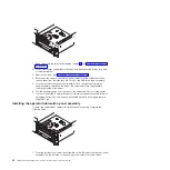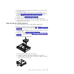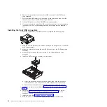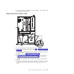
Removing the power backplane
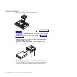
To remove the power backplane, complete the following steps.
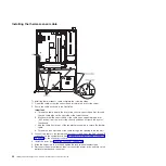
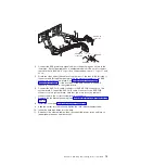
Screws
Power
backplane
1. Read the safety information that begins on page vii and “Installation guidelines”
2. Turn off the server and peripheral devices, and disconnect the power cord and
all external cables.
3. Remove the cover (see “Removing the cover” on page 46).
4. Remove the power supplies from the power-supply bays (see “Removing a
5. Make note of the routing for all power backplane cables; then, disconnect all
power backplane cables from the system board and other components.
6. Remove the system board (see “Removing the system board” on page 80).
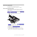
7. Remove the screws that secure the power backplane to the chassis; then, grasp
the power backplane and slide it toward the left side of the server.
8. Lift the power backplane out of the server.
9. If you are instructed to return the backplane, follow all packaging instructions,
and use any packaging materials for shipping that are supplied to you.
Installing the power backplane
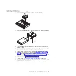
To install the power backplane, complete the following steps.
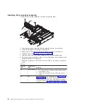
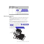
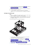
Screws
Power
backplane
76
IBM System x3610 Type 7942: Problem Determination and Service Guide
Summary of Contents for System x3610
Page 1: ...IBM System x3610 Type 7942 Problem Determination and Service Guide...
Page 2: ......
Page 3: ...IBM System x3610 Type 7942 Problem Determination and Service Guide...
Page 8: ...vi IBM System x3610 Type 7942 Problem Determination and Service Guide...
Page 32: ...14 IBM System x3610 Type 7942 Problem Determination and Service Guide...
Page 54: ...36 IBM System x3610 Type 7942 Problem Determination and Service Guide...
Page 143: ......
Page 144: ...Part Number 49Y0084 Printed in USA 1P P N 49Y0084...

