background image

Welcome. . .

Thank you for buying an
IBM xSeries server.

This server
contains information for setting
up and configuring your server.

For detailed information
about your server, view the

on the

You can also find the most
current information about your
server on the IBM Web site at:
http://www.ibm.com/pc/support

Installation Guide

User's Reference

Documentation CD.

Go to the Server Support

flow chart

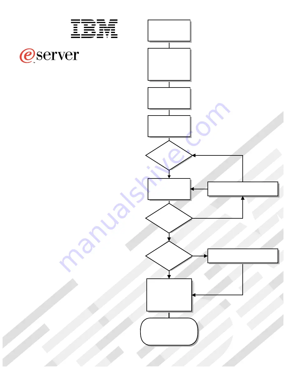
Cable the server

and options

Start the server

Install the server in

the rack, if required

Did the server

start correctly?

Yes

No

Use ServerGuide™

to set up and

configure hardware

Did configuration

complete?

Use

ServerGuide to

install operating

system?

Use ServerGuide to
install applications,
such as IBM systems
management software
and IBM ServeRAID
programs

System is ready to use.

Go to the Server Support

flow chart to register

and profile your server.

Go to the Web for instructions,
http://www.ibm.com/pc/support

No

Yes

Yes

No

Installation Guide

Install options:
• Drives
• Microprocessors
• Adapters
• Memory

xSeries 370

®


Summary of Contents for eServer 370 xSeries

Page 1: ...e server and options Start the server Install the server in the rack if required Did the server start correctly Yes No Use ServerGuide to set up and configure hardware Did configuration complete Use S...

Page 2: ...bleshooting information provided with your server to determine the cause of the problem and the action to take Flash the latest levels of BIOS service processor diagnostics and RAID code You can downl...

Page 3: ...IBM xSeries 370 Installation Guide...

Page 4: ...ct warranties and notices on page 57 First Edition March 2001 Copyright International Business Machines Corporation 2001 All rights reserved Note to U S Government Users Documentation related to restr...

Page 5: ...he installation 35 Cabling the server 36 Chapter 3 Server power controls and indicators 39 Turning on the server 39 Turning off the server 40 Controls and indicators 41 Front panel 43 Chapter 4 Config...

Page 6: ...iv xSeries 370 Installation Guide...

Page 7: ...s curit Vor der Installation dieses Produkts die Sicherheitshinweise lesen Prima di installare questo prodotto leggere le Informazioni sulla Sicurezza Lees voordat u dit product installeert eerst de...

Page 8: ...is evidence of fire water or structural damage Disconnect the attached power cords telecommunications systems networks and modems before you open the device covers unless instructed otherwise in the i...

Page 9: ...dule containing a lithium battery replace it only with the same module type made by the same manufacturer The battery contains lithium and can explode if not properly used handled or disposed of Do no...

Page 10: ...re no serviceable parts inside the device Use of controls or adjustments or performance of procedures other than those specified herein might result in hazardous radiation exposure DANGER Some laser p...

Page 11: ...on the power supply do not turn off the electrical current supplied to the device The device also might have more than one power cord To remove all electrical current from the device ensure that all p...

Page 12: ...where others can handle and possibly damage the device While the device is still in its static protective package touch it to an unpainted metal part of the system unit for at least two seconds This d...

Page 13: ...ormation about your xSeries 370 and other IBM server products at http www ibm com eserver xseries on the World Wide Web If you purchased a rack model of the xSeries 370 server use the Rack Installatio...

Page 14: ...gement PCI adapter upgrades when available Diagnostics upgrades when available Memory upgrades when available POST BIOS upgrades when available to update electrically erasable programmable read only m...

Page 15: ...mum configuration 1700 Btu hr Maximum configuration 7000 Btu hr Safety standards UL 1950 Third Edition CSA C22 2 No 950 95 EN 60950 and countries deviations IEC 950 NOM 019 Table 3 Acoustical noise em...

Page 16: ...ed just before a description of a potentially hazardous procedure step or situation Danger These notices indicate situations that can be potentially lethal or extremely hazardous to you A danger notic...

Page 17: ...ive 8 Dual inline memory module 9 Memory board 1 Memory board latches 11 Processor housing assembly 12 Processor housing assembly latch 13 Memory access panel 14 Memory access panel fastener 15 Front...

Page 18: ...stener 3 Processor cage 4 Spacers 5 LED card 6 Fan guard 7 Fan connector 8 Processor fail LED 9 Memory fail LED 1 Press To Show Fault button 11 Capacitor Testing LED 12 Processor fail LED 13 Processor...

Page 19: ...y 1 I O function card 2 Battery 3 Insulator 4 I O board protector shield 5 I O board 6 Adapter retention cover 7 I O housing 8 I O housing assembly latch 9 Adapter retention latch 1 Tab 11 Advanced Sy...

Page 20: ...8 xSeries 370 Installation Guide...

Page 21: ...or scarves to hang inside the server Remove all jewelry such as necklaces bracelets and loose fitting wrist watches Remove items from your shirt pocket such as pens and pencils that could fall into t...

Page 22: ...lug power LED for PCI slot green solid on PCI slot LED descriptions Each PCI slot has two lights associated with it one Attention Fail light and one Power On light Power On Light This light is on when...

Page 23: ...e If you install additional storage adapters and external hard disk drives and you do not want to change the startup hard disk drive you must install the adapters in PCI slots 1 through 9 The I O func...

Page 24: ...t install the operating system services for hot plug PCI support code To obtain the operating system hot plug PCI support code access http www ibm com pc support on the World Wide Web Installing a PCI...

Page 25: ...use for the adapter Note Check the instructions that come with the adapter for any requirements or restrictions Refer to the following illustration while you perform the following step 5 If you are i...

Page 26: ...he adapter retention cover 4 a Press outward on the adapter retention assembly where indicated by the arrow b Continue pressing on the assembly as described in step 7a and lift the adapter retention c...

Page 27: ...nto the expansion slot c If you are installing a full length adapter close the adapter retention cover 4 d Lower the tab 1 over the adapter Rotate the adapter retention latch 2 until it snaps in place...

Page 28: ...e a ServeRAID adapter to the internal hard disk drives in your server or to make this adapter a startup device you must install the ServeRAID adapter in PCI slot 10 11 or 12 Refer to your ServeRAID ad...

Page 29: ...connect all cables 1 from the I O function card 2 Note carefully where each cable is connected before you remove it Refer to the system label on the server cover for the connector locations on the I O...

Page 30: ...ion bracket that you removed in step 3a4 on page 17 by pressing in the fastener on the bracket 6 Insert the two screws that you removed in step 3a3 on page 17 7 Connect the cables that you disconnecte...

Page 31: ...and so on 4 Cache line interleaving can occur only if two memory boards are installed in the server This process allows the two memory boards to share a common address range with one memory board res...

Page 32: ...t the registered mode of operation 2 Install DIMMs with a maximum height of 4 32 cm 1 7 inches 3 Your server comes with one standard preinstalled memory board A and one or more DIMMs installed on this...

Page 33: ...er and peripheral devices and disconnect all external cables and power cords 3 Remove the front bezel 4 Remove the server memory access panel a Pull out the two plastic fasteners 1 on the memory acces...

Page 34: ...ive package containing the DIMM to any unpainted metal surface on the server Then remove the DIMM from the package Attention To avoid breaking the retaining clips or damaging the DIMM connectors handl...

Page 35: ...the latches b Push the latches 1 until they close and lock in place Attention To ensure proper EMC containment and cooling for your server reinstall the memory access panel before turning on the serve...

Page 36: ...pers on hard disk drives 4 All the internal hot swap drives in your server have automatic termination Attention To avoid damage to a hard disk drive do not remove the drive from the hot swap bay until...

Page 37: ...assembly into the bay until the drive stops g Push the tray handle to the closed locked position 6 Check the hard disk drive status indicators to verify that the hard disk drives are operating properl...

Page 38: ...es If you plan to use the processor serial number security feature you must change the setting of the Processor Serial Number Access menu choice in the Advanced Setup menu of the Configuration Setup U...

Page 39: ...tional processor daughterboard B install them in the following order B1 B3 B2 B4 To install a processor 1 Review the information in Safety on page v through Handling static sensitive devices on page x...

Page 40: ...op of the processor housing assembly Attention Do not lift the processor housing assembly by the latches d Grasp the bottom sides of the processor housing assembly Lift and slide the assembly out of t...

Page 41: ...a Pull the processor terminator card latches 4 so that they rotate to the unlocked position b Remove the processor terminator card 5 from the processor connector c Store the processor terminator card...

Page 42: ...e arrows on the terminators must face toward the large connector on the processor housing assembly and away from the fan guard 12 Reinstall the processor cage cover by inserting the cover tabs into th...

Page 43: ...ign the tabs on the bottom edge of the fans with the matching slots in the server chassis 2 When you have the fans correctly seated press the fasteners in the top center of the fans to secure the fans...

Page 44: ...with a processor 11 in connector A1 The optional processor cage is item 5 Note When you install the optional processor daughterboard you must also install the two cache coherency filter cards that com...

Page 45: ...cal slots between the two processor daughterboards on the processor controller board Refer to the layout of the processor controller card in the User s Reference on the IBM xSeries Documentation CD fo...

Page 46: ...e sure the processor bus to core ratio is set correctly see Table 7 on page 35 For example if you have a 700 MHz processor installed and the system bus speed is 100 MHz the default be sure that the ju...

Page 47: ...f a processor becomes available for your model use these jumper settings Table 7 Processor controller board jumper Jumper name Description 5 Processor core frequency selection The default core bus fra...

Page 48: ...45 connectors at both ends An EIA TIA 568 category 5 cable must be used for 100BASE TX connectors to meet various standards including electromagnetic compatibility 3 Connect the power cord s to the se...

Page 49: ...pped with your server This Y cable can be used to attach to a modem that is dedicated to communication with the Advanced System Management PCI adapter 7 Advanced System Management Interconnect port co...

Page 50: ...38 xSeries 370 Installation Guide...

Page 51: ...e branch circuit c 20 amps or greater you may connect up to three power cords to the same branch circuit You can turn the server on by pressing the Power Control button on the front of the server 1 Tu...

Page 52: ...f the server and places the server in standby mode This feature can be used if the operating system hangs Note After turning off the server wait at least five seconds before pressing the Power Control...

Page 53: ...front panel and enable the system error light to stop flashing 3 Enter button Press this button to perform an action on system monitoring messages that appear on the front panel 4 CD ROM drive in use...

Page 54: ...ject a diskette from the drive 9 Diskette drive in use light When this light is lit the diskette drive is being accessed 1 Power control button Press this button to manually turn the server on or off...

Page 55: ...n about the condition displays on the information message panel 3 SCSI hard disk drive in use light This green light is on when there is activity on a hard disk drive Attention If the System Power Lig...

Page 56: ...44 xSeries 370 Installation Guide...

Page 57: ...input output system BIOS code that comes with your server You can use this program to configure serial and parallel port assignments change interrupt request IRQ settings change the drive startup seq...

Page 58: ...d View the README file to review installation tips about your NOS and adapter e Start the setup and hardware configuration programs f Start the NOS installation You will need your copy of the NOS CD N...

Page 59: ...lay screen If this occurs and the Boot Fail Count feature in the Start Options of the Configuration Setup Utility is set to Enabled its default setting you must restart the server three times to force...

Page 60: ...ssor Check the installation of your microprocessors 289 Failing DIMM was disabled Verify that your memory is correct for your server and that it is installed properly 301 303 Keyboard and keyboard con...

Page 61: ...nstalled drives or cannot install NOS Ensure that there are no duplicate SCSI IDs or IRQ assignments Ensure that the hard disk drive is connected properly The Operating System Installation program con...

Page 62: ...ation Setup Utility program to verify that the CD ROM drive is enabled Diskette drive problems Action Diskette Drive In Use light stays on or the system bypasses the diskette drive If there is a diske...

Page 63: ...you start some application programs Verify that the primary monitor cable is connected to the video port Be sure that you installed the necessary drivers for the application Blank screen Verify that...

Page 64: ...y that the mouse or pointing device cable is securely connected 2 Verify that the device drivers are installed correctly 3 Attach another mouse or pointing device to the pointing device port Note The...

Page 65: ...nd the test programs found no problem have the system and the option serviced If the failing option is a SCSI option verify that 1 The cables for all external SCSI options are connected correctly 2 Th...

Page 66: ...rectly in your operating system or application program 4 You have assigned the printer port correctly using the Configuration Setup Utility program If the items above are correct and the printer still...

Page 67: ...If you received any error messages when using the software program refer to the information supplied with the software for a description of the messages and solutions to the problem If the items above...

Page 68: ...56 xSeries 370 Installation Guide...

Page 69: ...ise the following warranties apply only in the country where you acquire the Machine Nothing in this Statement of Warranty affects any statutory rights of consumers that cannot be waived or limited by...

Page 70: ...reseller will inform you of the available types of service for a Machine based on its country of installation IBM may repair the failing Machine or exchange it at its discretion When warranty service...

Page 71: ...G LOST PROFITS OR SAVINGS EVEN IF IBM ITS SUPPLIERS OR YOUR RESELLER IS INFORMED OF THEIR POSSIBILITY SOME JURISDICTIONS DO NOT ALLOW THE EXCLUSION OR LIMITATION OF INCIDENTAL OR CONSEQUENTIAL DAMAGES...

Page 72: ...vided for a Machine under warranty such as assistance via telephone with how to questions and those regarding Machine set up and installation will be provided WITHOUT WARRANTIES OF ANY KIND Warranty S...

Page 73: ...plies to IBM s suppliers and your reseller It is the maximum for which IBM its suppliers and your reseller are collectively responsible UNDER NO CIRCUMSTANCES IS IBM LIABLE FOR ANY OF THE FOLLOWING 1...

Page 74: ...n warranty service for that Machine in any of those countries from either 1 an IBM reseller approved to perform warranty service or 2 from IBM If you purchased an IBM Personal Computer Machine in Alba...

Page 75: ...claim Applicability of suppliers and resellers unchanged The following paragraph is added at the end of this Section IBM s entire liability and your sole remedy whether in contract or in tort in resp...

Page 76: ...warranty relates to right to sell quiet possession or clear title or the goods are of a kind ordinarily acquired for personal domestic or household use or consumption then none of the limitations in t...

Page 77: ...om IBM IBM is liable for no more than items 1 and 2 unchanged GERMANY The IBM Warranty for Machines The following replaces the first sentence of the first paragraph of this Section The warranty for an...

Page 78: ...ed to the charge paid by you for the individual Machine that is the subject of your claim from IBM TURKIYE Production Status The following replaces this Section IBM fulfils customer orders for IBM Mac...

Page 79: ...RRANTIES OF MERCHANTABILITY OR FITNESS FOR A PARTICULAR PURPOSE Some jurisdictions do not allow disclaimer of express or implied warranties in certain transactions therefore this statement may not app...

Page 80: ...ctly The foregoing is a Year 2000 Readiness Disclosure Trademarks The following terms are trademarks of the IBM Corporation in the United States or other countries or both The following terms are trad...

Page 81: ...operated in a commercial environment This equipment generates uses and can radiate radio frequency energy and if not installed and used in accordance with the instruction manual may cause harmful inte...

Page 82: ...9 336 EEC on the approximation of the laws of the Member States relating to electro magnetic compatibility Attention This is a Class A product In a domestic environment this product may cause radio in...

Page 83: ...m Benin Bulgaria Burkina Faso Burundi Cameroon Central African Rep Chad China Macau S A R Czech Republic Egypt Finland France French Guiana Germany Greece Guinea Hungary Iceland Indonesia Iran Ivory C...

Page 84: ...72 xSeries 370 Installation Guide...

Page 85: ...beep code descriptions 47 BIOS basic input output system SCSI B detect jumper J19 17 blank screen 51 bus master capability 36 bus number assignments 11 C cables connecting SCSI to ServeRAID adapter 1...

Page 86: ...ht 42 problems 50 display See monitor DMA direct memory access drive in use light 41 42 SCSI ID assignments 24 status indicators 41 drivers device for network adapters 16 dual inline memory module DIM...

Page 87: ...controller 11 integrated voltage regulator 2 interleaving cache line 19 intermittent problems 52 interrupt levels assigning PCI 11 interrupt request IRQ assigning interrupt levels 11 introduction 1 J...

Page 88: ...els 11 hot plug adapters 9 PCI peripheral component interconnect architecture continued installing hot plug adapters 12 peripheral component interconnect PCI architecture See PCI peripheral component...

Page 89: ...dures See also password processor serial number access 26 Serial Bus Universal See Universal Serial Bus USB serial number processor 26 server 1 serial port location 36 problems 53 server adding memory...

Page 90: ...t mode 2 United Kingdom safety information vii telephone line requirements vii United Kingdom electronic emission Class A notice 70 United States safety information vii United States electronic emissi...

Page 91: ......

Page 92: ...IBM Part Number 25P1505 Printed in the United States of America on recycled paper containing 10 recovered post consumer fiber 25P15 5...

Reviews: