


Chapter 4. Cabling the switch module and the SFP+ module
21
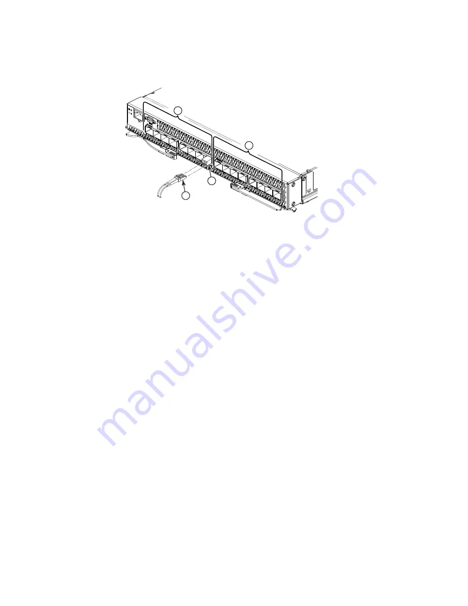
FIGURE 10
Fiber optic cable insertion
3. Check the LEDs on the switch module. When the switch module is operating correctly, the
green link LED is lit. For information about the status of the switch module LEDs, see
,
“Chapter 5. Information panels, LEDs, and external ports,”
on
page 23
.
Disconnecting the SFP+ module cable
To disconnect the SFP+ module cable, complete the following steps:
1. Squeeze the release tabs and gently pull the fiber optic cable from the SFP+ module.
2. Replace the protective caps on the ends of the fiber optic cable.
Connecting the RJ-45 Ethernet cable
The RJ-45 Ethernet cable can be connected to the RJ-45 port.
To connect the RJ-45 connector to the switch module, push the connector into the port connector
until it clicks into place, as shown in the following illustration.
1
FC ports
3
Fiber optic cable
2
CEE ports
4
SFP+ module
2
1
3
4
Summary of Contents for Brocade FCoE
Page 1: ...Brocade FCoE Switch Module for IBM BladeCenter Installation and User s Guide ...
Page 2: ......
Page 8: ...viii Brocade FCoE Switch Module for IBM BladeCenter Installation and User Guide ...
Page 14: ...xiv Brocade FCoE Switch Module for IBM BladeCenter Installation and User Guide ...
Page 28: ...14 Brocade FCoE Switch Module for IBM BladeCenter Installation and User Guide ...
Page 52: ...38 Brocade FCoE Switch Module for IBM BladeCenter Installation and User Guide ...
Page 56: ...42 Brocade FCoE Switch Module for IBM BladeCenter Installation and User Guide ...
Page 70: ...56 Brocade FCoE Switch Module for IBM BladeCenter Installation and User Guide ...
Page 74: ...60 Brocade FCoE Switch Module for IBM BladeCenter Installation and User Guide ...
Page 75: ...1 ...
Page 76: ...2 Part Number 60Y1582 Printed in USA IP P N 60Y1582 60Y1582 ...


