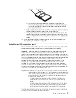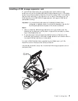
2. Shut down the operating system, turn off the blade server, and remove the
blade server from the BladeCenter unit. See “Removing the blade server from
the BladeCenter unit” on page 20 for instructions.
3. Carefully lay the blade server on a flat, non-conductive surface.
4. Open the blade server cover (see “Opening the blade server cover” on
page 21 for instructions).
5. Remove the bezel assembly (see “Removing the blade server bezel assembly”
on page 22 for instructions).
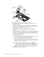
6. Locate the microprocessor socket on the system board.
7. Remove the heat-sink filler.
8. Install the microprocessor:
a. Remove the protective cover, tape, or label from the surface of the
microprocessor socket, if one is present.
b. Touch the static-protective package containing the new microprocessor to
any
unpainted
metal surface on the BladeCenter chassis or any
unpainted
surface on any other grounded rack component; then, remove the
microprocessor from the package.
Chapter 3. Installing options
27
Summary of Contents for BladeCanter HS20
Page 3: ...BladeCenter HS20 Type 8832 Installation and User s Guide ERserver...
Page 7: ...Japanese Voluntary Control Council for Interference VCCI statement 83 Index 85 Contents v...
Page 8: ...vi BladeCenter HS20 Type 8832 Installation and User s Guide...
Page 14: ...xii BladeCenter HS20 Type 8832 Installation and User s Guide...
Page 26: ...12 BladeCenter HS20 Type 8832 Installation and User s Guide...
Page 32: ...18 BladeCenter HS20 Type 8832 Installation and User s Guide...
Page 58: ...44 BladeCenter HS20 Type 8832 Installation and User s Guide...
Page 66: ...52 BladeCenter HS20 Type 8832 Installation and User s Guide...
Page 68: ...54 BladeCenter HS20 Type 8832 Installation and User s Guide...
Page 98: ...84 BladeCenter HS20 Type 8832 Installation and User s Guide...
Page 102: ...88 BladeCenter HS20 Type 8832 Installation and User s Guide...
Page 103: ......
Page 104: ...Part Number 59P6556 Printed in U S A 1P P N 59P6556...


