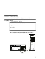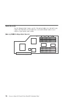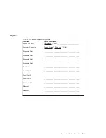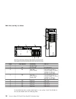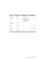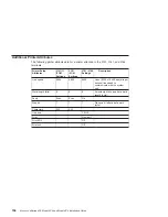
Component LEDs
Individual LEDs are located on or near the failing components. The LEDs are located
either on the component itself or on the carrier of the component (for example: memory
card, fan, memory module, CPU). LEDs are either green or amber.
Green colored LEDs when blinking indicates that the system or system component is in
the standby state (waiting to receive or send information). A steady lit green colored
LED indicates that the system or component is operating normally.
Amber colored LEDs indicate a fault or identify condition. If your system or one of the
components on your system has a lit amber colored LED identify the problem and take
the appropriate action to restore the system to normal.
Component
LED
Function
Location
LED Color
OFF
ON
Power and Packaging LEDs
Rack Indicator
Drawer Sum
Top of Rack
Amber (1x)
Normal
Fault
AC Input
Green (1x)
No Input
AC Good
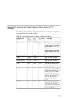
System Unit (Front
and Back)
Attention
Operator Panel
+ Rear
Amber (2x) Normal
Fault
Power
Operator Panel
+ Rear
Green (2x)
No AC
System On
If blinking =
v
Standby - slow
v
transition of power on/off -
fast
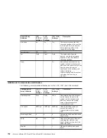
Fans
Identify
Fan Top
Amber (4x) Normal
Fault
Power Supply (AC)
Input Source
Power Supply
Front + Top
Green (1x)
No Input
Input Good
Fault
Power Supply
Front + Top
Amber (1x) Normal
Fault
If blinking = Power Control
Comm. Failed
DC Output
Good
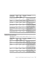
Power Supply
Front + Top
Green (1x)
DC Off
DC Good
If blinking = Standby
Disk Drives
(DASD)
Activity
DASD Board
Green (4x)
No Activity
Activity
Remove
Identify
DASD Board
Amber (4x) Meets RPA Hot Swap
Requirement
Optional Media
No LEDs
142
Eserver
pSeries 630 Model 6C4 and Model 6E4 Installation Guide
Summary of Contents for @Server pSeries 630 6C4
Page 1: ...pSeries 630 Model 6C4 and Model 6E4 Installation Guide SA38 0605 01 ERserver IBM...
Page 2: ......
Page 3: ...pSeries 630 Model 6C4 and Model 6E4 Installation Guide SA38 0605 01 ERserver IBM...
Page 12: ...x Eserver pSeries 630 Model 6C4 and Model 6E4 Installation Guide...
Page 14: ...xii Eserver pSeries 630 Model 6C4 and Model 6E4 Installation Guide...
Page 22: ...6 Eserver pSeries 630 Model 6C4 and Model 6E4 Installation Guide...
Page 64: ...48 Eserver pSeries 630 Model 6C4 and Model 6E4 Installation Guide...
Page 148: ...132 Eserver pSeries 630 Model 6C4 and Model 6E4 Installation Guide...
Page 152: ...136 Eserver pSeries 630 Model 6C4 and Model 6E4 Installation Guide...
Page 156: ...140 Eserver pSeries 630 Model 6C4 and Model 6E4 Installation Guide...
Page 166: ...150 Eserver pSeries 630 Model 6C4 and Model 6E4 Installation Guide...
Page 179: ......
Page 180: ...IBMR Part Number 00P3937 Printed in U S A August 2002 SA38 0605 01 1P P N 00P3937...


