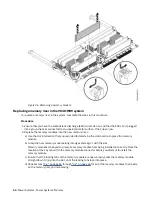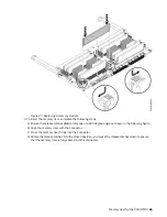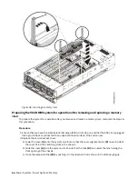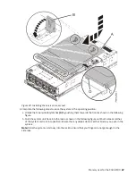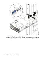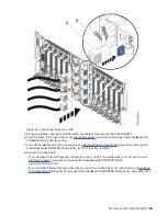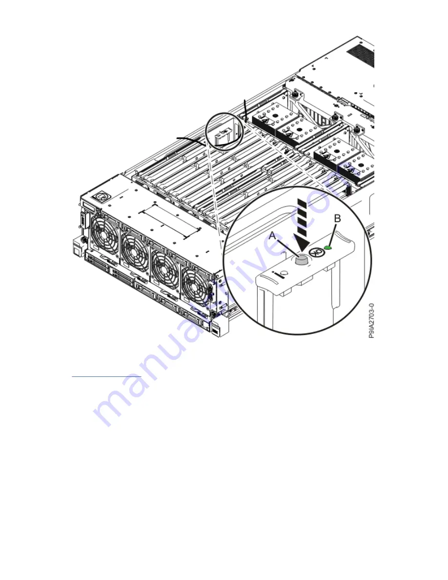
Figure 43. Activating the identify LED
9. Locate the amber LED for the failed memory riser. Make a note of which memory riser is lit.
Figure 44 on page 62 shows the locations (A) of the memory riser LEDs.
Memory riser for the 9040-MR9 61
Summary of Contents for 9040-MR9
Page 1: ...Power Systems Memory modules for the 9040 MR9 IBM ...
Page 4: ...iv ...
Page 14: ...xiv Power Systems Power Systems Memory ...
Page 17: ...Figure 1 Removing the power cords L003 or or Memory modules for the 9040 MR9 3 ...
Page 30: ...or or or or 16 Power Systems Power Systems Memory ...
Page 46: ...Figure 23 Removing the power cords L003 or or 32 Power Systems Power Systems Memory ...
Page 59: ...Figure 32 Removing the power cords L003 or or Memory riser for the 9040 MR9 45 ...
Page 70: ...Figure 40 Removing the power cords L003 or or 56 Power Systems Power Systems Memory ...
Page 86: ...or or or or 72 Power Systems Power Systems Memory ...
Page 105: ......
Page 106: ...IBM ...


