IBM 9006-12C Manual Download Page 37

3.

Replace the fan holder into the chassis. Align the holes in the fan holder with the pins in the bottom
of the chassis as shown in Figure 20 on page 22. For the fan holder near the cover switch, temporarily
move the cover switch wires out of the way. When the fan holder is seated into the system, replace
the wires next to the fan holder.

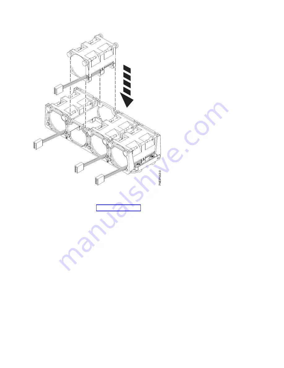
Figure 19. Replacing a fan

Removing and replacing parts in the 9006-12C

21

Summary of Contents for 9006-12C

Page 1: ...Power Systems Servicing the IBM Power System LC921 9006 12C IBM...

Page 2: ......

Page 3: ...Power Systems Servicing the IBM Power System LC921 9006 12C IBM...

Page 4: ...y Notices manual G229 9054 and the IBM Environmental Notices and User Guide Z125 5823 This edition applies to IBM Power Systems servers that contain the POWER9 processor and to all associated models C...

Page 5: ...the 9006 12C 55 Removing a system processor module from the 9006 12C system 55 Replacing a system processor module for the 9006 12C 61 Removing and replacing the time of day battery in the 9006 12C 69...

Page 6: ...itional information 95 Drive installation details for the 9006 12C system 95 Notices 97 Accessibility features for IBM Power Systems servers 98 Privacy policy considerations 99 Trademarks 100 Electron...

Page 7: ...dditional copies of safety information documentation can be obtained by calling the IBM Hotline at 1 800 300 8751 German safety information Das Produkt ist nicht f r den Einsatz an Bildschirmarbeitspl...

Page 8: ...nect 1 Turn off everything unless instructed otherwise 2 For AC power remove the power cords from the outlets 3 For racks with a DC power distribution panel PDP turn off the circuit breakers located i...

Page 9: ...mperatures will exceed the manufacturer s recommended ambient temperature for all your rack mounted devices v Do not install a unit in a rack where the air flow is compromised Ensure that air flow is...

Page 10: ...e potential hazards v Verify that the route that you choose can support the weight of the loaded rack cabinet Refer to the documentation that comes with your rack cabinet for the weight of a loaded ra...

Page 11: ...DANGER Rack mounted devices are not to be used as shelves or work spaces L002 L003 1 2 or 1 2 or 1 2 3 4 or Safety notices ix...

Page 12: ...be equipped with multiple AC power cords or multiple DC power cables To remove all hazardous voltages disconnect all power cords and power cables L003 L007 CAUTION A hot surface nearby L007 L008 x Pow...

Page 13: ...tacle Although shining light into one end and looking into the other end of a disconnected optical fiber to verify the continuity of optic fibers many not injure the eye this procedure is potentially...

Page 14: ...rhanging load v Do not use on uneven surface incline or decline major ramps v Do not stack loads v Do not operate while under the influence of drugs or alcohol v Do not support ladder against LIFT TOO...

Page 15: ...ing interfaces only Type 2 or Type 4 ports as described in GR 1089 CORE and require isolation from the exposed OSP cabling The addition of primary protectors is not sufficient protection to connect th...

Page 16: ...xiv Power Systems Servicing the IBM Power System LC921 9006 12C...

Page 17: ...contact the provider of the part or your next level of support DANGER When working on or around the system observe the following precautions Electrical voltage and current from power telephone and com...

Page 18: ...ch the power cords to the outlets 5 For racks with a DC power distribution panel PDP restore the power from the Customer s DC power source and turn on the circuit breakers located in the PDP 6 Turn on...

Page 19: ...to removing the product from ESD packaging and installing or replacing hardware touch an unpainted metal surface of the system for a minimum of 5 seconds If at any point in this service process you m...

Page 20: ...in the previous step reinstall the drive in the bay you removed it from and check the other drive bays 6 Remove a drive from the tray v For a 3 5 inch drive unfasten the drive from the sides of the tr...

Page 21: ...e retention spring A c Lift the 2 5 inch drive B out of the tray as shown in Figure 4 on page 6 d Close the retention spring e Turn the tray right side up Figure 2 Removing the 3 5 inch drive from the...

Page 22: ...the electrostatic discharge ESD wrist strap on and that the ESD clip is plugged into a ground jack or connected to an unpainted metal surface If not do so now 2 Install a drive into the tray Orient th...

Page 23: ...e 8 c Place the 2 5 inch drive A into the tray aligning the pins with the screw holes in the drive d When the pins are aligned close the retention spring allowing the pins to secure the drive in the t...

Page 24: ...nt Ensure that the drive is fully seated and is all the way into the system 4 Lock the drive bay handle A by pushing in the handle release until it locks at B as shown in Figure 8 on page 9 Figure 7 M...

Page 25: ...Hat Enterprise Linux RHEL version 7 2 To run the rescan command in the REHL version 7 2 operating system log in to the system as the root user and run the command rescan scsi bus sh a The rescan scsi...

Page 26: ...ging your hardware v When you use an ESD wrist strap follow all electrical safety procedures An ESD wrist strap is used for static control It does not increase or decrease your risk of receiving elect...

Page 27: ...ase or decrease your risk of receiving electric shock when using or working on electrical equipment v If you do not have an ESD wrist strap just prior to removing the product from ESD packaging and in...

Page 28: ...ant to refer to Adding a Storage Device or Path https access redhat com documentation en US Red_Hat_Enterprise_Linux 7 html Storage_Administration_Guide logical unit add remove html 5 Load or restore...

Page 29: ...aging and installing or replacing hardware touch an unpainted metal surface of the system for a minimum of 5 seconds If at any point in this service process you move away from the system it is importa...

Page 30: ...Figure 13 on page 15 a Remove the two screws A one from each side from the top of the disk drive backplane b Pivot the top of the disk drive backplane towards the rear of the system to free the backp...

Page 31: ...now 2 Remove the replacement disk drive backplane and cables from the protective plastic envelope 3 Move the cables from the old disk drive backplane to the new card 4 Replace the disk drive backplan...

Page 32: ...on page 6 6 Using the labels replace the drive signal cables A and drive power cable B into the system backplane as shown in Figure 15 on page 17 Ensure that the cable latch clip snaps into place on t...

Page 33: ...emove and replace internal parts on page 80 Removing and replacing fans in the 9006 12C Learn how to remove and replace the fans in the IBM Power System LC921 9006 12C system Removing a system fan fro...

Page 34: ...electrical safety procedures An ESD wrist strap is used for static control It does not increase or decrease your risk of receiving electric shock when using or working on electrical equipment v If you...

Page 35: ...ctor clip B and carefully pull up the connector A from the system backplane as shown in Figure 18 on page 20 Do not pull on the wires Feed the cable through the fan holder Figure 17 Removing a fan Rem...

Page 36: ...ist strap on and that the ESD clip is plugged into a ground jack or connected to an unpainted metal surface If not do so now 2 With the fan holder lifted push the fan into the housing as shown in Figu...

Page 37: ...of the chassis as shown in Figure 20 on page 22 For the fan holder near the cover switch temporarily move the cover switch wires out of the way When the fan holder is seated into the system replace th...

Page 38: ...4 Connect the fan cable to the system backplane as shown in Figure 21 on page 23 Figure 20 Aligning the fan holder 22 Power Systems Servicing the IBM Power System LC921 9006 12C...

Page 39: ...06 12C system Learn how to remove the graphics processing unit from the IBM Power System LC921 9006 12C system Before you begin Power off the system and place it in the service position For instructio...

Page 40: ...system for a minimum of 5 seconds If at any point in this service process you move away from the system it is important to again discharge yourself by touching an unpainted metal surface for at least...

Page 41: ...to replace a graphics processing unit in the IBM Power System LC921 9006 12C system Procedure 1 Ensure that you have the electrostatic discharge ESD wrist strap on and that the ESD clip is plugged in...

Page 42: ...s shown in Figure 26 a Ensure that the PCIe holder release pins B are retracted so the arrows point into the system b Use the alignment pins A and slots to help you properly insert the riser cards and...

Page 43: ...y in the 9006 12C Learn how to remove and replace memory in the IBM Power System LC921 9006 12C system Before you begin Power off the system and place it in the service position For instructions see P...

Page 44: ...in this service process you move away from the system it is important to again discharge yourself by touching an unpainted metal surface for at least 5 seconds before you continue with the service pro...

Page 45: ...is keyed to prevent it from being installed incorrectly Note the location of the key tab within the memory connector before you attempt to install it b Press firmly on each side of the memory DIMM unt...

Page 46: ...lace it Insert the edge of the baffle into the fan support Then carefully press the baffle down into place Figure 30 Inserting the memory DIMM Figure 31 Installing the processor air baffle 30 Power Sy...

Page 47: ...e to prevent the electrostatic discharge from damaging your hardware v When you use an ESD wrist strap follow all electrical safety procedures An ESD wrist strap is used for static control It does not...

Page 48: ...shown in Figure 33 c Lift the PCIe adapter riser at points A and B from the system backplane 5 If the PCIe adapter to remove is in positions 2 3 or 4 you must remove the PCIe cage and riser a Remove...

Page 49: ...m the adapter c If the riser contains a GPU remove the power cable A from the system backplane as shown in Figure 35 on page 34 Using your thumb press the release latch on the connector to remove the...

Page 50: ...shown in Figure 36 a Remove the screw that secures the PCIe adapter to the PCIe cage b Remove the PCIe adapter from the riser Figure 35 Unplugging the GPU power cable Figure 36 Removing a PCIe adapte...

Page 51: ...edure 1 Ensure that you have the electrostatic discharge ESD wrist strap on and that the ESD clip is plugged into a ground jack or connected to an unpainted metal surface If not do so now 2 Refer to t...

Page 52: ...lstock to the PCIe adapter d Insert the adapter into the PCIe riser e If you installed the support bracket for the PCIe adapter fasten the special support tailstock to that bracket 4 If you are workin...

Page 53: ...pter before inserting the adapter b Insert the adapter A into the riser B as shown in Figure 42 aligning it properly and inserting it fully into the slot Secure the adapter tail stock with 1 or 2 scre...

Page 54: ...9 1 Ensure that the PCIe holder release pins B are retracted so the arrows point into the system 2 Use the alignment pins A and slots to help you properly insert the riser cards and replace the cover...

Page 55: ...tic tip screwdriver to remove and replace the screws Removing the system backplane in the 9006 12C Learn how to remove the system backplane in the IBM Power System LC921 9006 12C system Before you beg...

Page 56: ...c discharge ESD wrist strap to the front ESD jack to the rear ESD jack or to an unpainted metal surface of your hardware to prevent the electrostatic discharge from damaging your hardware v When you u...

Page 57: ...label and remove the PCIe risers and adapters For instructions see Removing a PCIe adapter from the 9006 12C system on page 31 Remove the large PCIe riser first 7 Remove the 12 screws that support the...

Page 58: ...ing the disk drive backplane from the 9006 12C on page 12 9 Remove the operator panel cable from the system backplane as shown in Figure 48 Figure 47 Processor socket screws on bottom of chassis Figur...

Page 59: ...oving the front cables out of the way and carefully holding the processor heat sink move the system backplane slightly forwards and up to remove it See Figure 50 on page 44 Figure 49 Screw locations T...

Page 60: ...l surface If not do so now 2 Remove the replacement system backplane from the static protective package and place it on an ESD mat The following steps move the system processor module from the old sys...

Page 61: ...side down on a clean surface 6 Inspect the thermal interface material TIM for visible signs of damage If you see folds tears bends or if you have doubts about the TIM replace it Figure 51 Loosening he...

Page 62: ...e from the old system backplane socket to transfer it to the new system backplane socket 10 Lower the tool and system processor module onto the socket Align the beveled corner A of the tool with the b...

Page 63: ...uide pins are properly aligned squeeze and hold the two blue release tabs A together until a firm stop is reached as shown in Figure 55 on page 48 Then lift the tool off the system processor module Fi...

Page 64: ...sink over the system processor module ensuring that the holes in the heat sink A align with the two guide pins B on the socket as shown in Figure 56 on page 49 Figure 55 Removing the system processor...

Page 65: ...er the heat sink B and tighten the load arm screw with a 3 Phillips screw driver as shown in Figure 57 on page 50 Note Do not overtighten the load arm screw Figure 56 Installing the heat sink Removing...

Page 66: ...Moving the front cables out of the way and carefully holding the processor heat sink lower the system backplane into the chassis then slide it slightly back See Figure 58 on page 51 Figure 57 Tighteni...

Page 67: ...5 Align and screw the 14 screws into the system backplane The screw locations are shown in Figure 59 on page 52 Figure 58 Replacing the system backplane Removing and replacing parts in the 9006 12C 51...

Page 68: ...Replacing the disk drive backplane in the 9006 12C on page 15 17 Replace the operator panel cable into the system backplane as shown in Figure 60 on page 53 Figure 59 Screw locations The two screws a...

Page 69: ...sor sockets a Turn the system over upside down b Replace the 12 screws from the bottom The screw locations are shown in Figure 61 on page 54 c Turn the system over right side up Figure 60 Replacing th...

Page 70: ...a system fan in the 9006 12C on page 20 21 Using your labels replace the memory DIMMs For instructions see Removing and replacing memory in the 9006 12C on page 27 22 Install the processor air baffle...

Page 71: ...the electrostatic discharge ESD wrist strap The ESD wrist strap must be connected to an unpainted metal surface until the service procedure is completed and if applicable until the service access cov...

Page 72: ...arm screw A of the system processor heat sink B that you are removing with a 3 Phillips screw driver The load arm pivots up in the direction that is shown in Figure 65 on page 57 Figure 63 Opening the...

Page 73: ...6 Place the heat sink upside down on a clean surface 7 Inspect the system processor socket area and remove any dust or debris use a can of compressed air Figure 65 Loosening heat sink load arm screw F...

Page 74: ...down on the tool to lock the system processor module into the tool as shown in Figure 68 on page 59 The tool drops slightly when you push down on the processor module so that the jaws can grab the bo...

Page 75: ...e packaging as shown in Figure 69 on page 60 Setting the system processor module at an angle on the top cover of the system processor module packaging will make it easier to pick up and place in the p...

Page 76: ...to release the system processor module from the tool as shown in Figure 70 on page 61 Figure 69 Placing the processor at an angle on the top cover of the packaging 60 Power Systems Servicing the IBM...

Page 77: ...o a ground jack or connected to an unpainted metal surface If not do so now 2 Inspect the system processor socket area and remove any dust or debris use a can of compressed air 3 Remove the replacemen...

Page 78: ...page 63 The tool drops slightly when you push down on the processor module so that the jaws can grab the bottom of the module Make sure that both of the tool jaws are locked on the system processor mo...

Page 79: ...ove any dust or debris use a can of compressed air 6 Lift the system processor module from the packaging tray as shown in Figure 73 on page 64 Figure 72 Locking the system processor module into the to...

Page 80: ...care to lower the tool evenly without tilting the tool Do not attempt to slide the tool and the system processor module in any direction while the system processor module is touching the socket If the...

Page 81: ...rly aligned squeeze and hold the two blue release tabs A together until a firm stop is reached as shown in Figure 75 on page 66 Then lift the tool off the system processor module Figure 74 Installing...

Page 82: ...sink Carefully lower the heat sink over the system processor module ensuring that the holes in the heat sink A align with the two guide pins B on the socket as shown in Figure 76 on page 67 Figure 75...

Page 83: ...er the heat sink B and tighten the load arm screw with a 3 Phillips screw driver as shown in Figure 77 on page 68 Note Do not overtighten the load arm screw Figure 76 Installing the heat sink Removing...

Page 84: ...tem processor module that you replaced by the edges and lift it off the shipping cover Align the beveled corner of the module A to the corner of the tray with the triangle B and place it in the tray a...

Page 85: ...stem Before you begin Power off the system and place it in the service position For instructions see Preparing the 9006 12C system to remove and replace internal parts on page 78 Procedure 1 Attach th...

Page 86: ...r at least 5 seconds before you continue with the service process 2 If the time of day battery is covered by a PCIe adapter move the adapter out of the way For instructions see Removing a PCIe adapter...

Page 87: ...surface of your hardware to prevent the electrostatic discharge from damaging your hardware v When you use an ESD wrist strap follow all electrical safety procedures An ESD wrist strap is used for sta...

Page 88: ...plugged in properly What to do next Prepare the system for operation For instructions see Preparing the 9006 12C system for operation after you remove and replace internal parts on page 80 Figure 82...

Page 89: ...ower distribution panel PDP disconnect the customer s DC power source to the PDP v When connecting power to the product ensure all power cables are properly connected For racks with AC power connect a...

Page 90: ...he rack cabinet v To avoid hazardous conditions due to uneven mechanical loading always install the heaviest devices in the bottom of the rack cabinet Always install servers and optional devices start...

Page 91: ...t the new feature See IBM Prerequisite 2 If you are installing or replacing something that might put your data at risk ensure wherever possible that you have a current backup of your system or logical...

Page 92: ...the following states Solid blue indicates that the local UID button was pressed Flashing blue indicates that a remote UID command was run Solid red indicates that the system is overheated Flashing re...

Page 93: ...form Management Interface IPMI program to turn on the blue identify LED to help you find the IBM Power System LC921 9006 12C or IBM Power System LC922 9006 22C system that needs servicing Procedure Us...

Page 94: ...ical safety procedures An ESD wrist strap is used for static control It does not increase or decrease your risk of receiving electric shock when using or working on electrical equipment v If you do no...

Page 95: ...bles To remove all hazardous voltages disconnect all power cords and power cables L003 L005 CAUTION Hazardous energy present Voltages with hazardous energy might cause heating when shorted with metal...

Page 96: ...s plugged into a ground jack or connected to an unpainted metal surface If not do so now 2 Replace the service access cover For instructions see Installing the service access cover on an 9006 12C syst...

Page 97: ...tems About this task Attention For safety airflow purposes and thermal performance the service access cover must be installed and fully seated before you power on the system You can use this procedure...

Page 98: ...pairs coming The P setting instructs the system to shut down and then power down The indicates the time in minutes before the shutdown occurs Drive commands for 9006 12C or 9006 22C Learn about the st...

Page 99: ...p the file then for RHEL 1 Navigate to the linux ppc folder then to the Little Endian folder 2 Install the package by running this command where x xx x equals the version of the utility rpm ivh StorCL...

Page 100: ...To turn the drive light on sas3ircu controller_ locate Enclosure Bay ON And off sas3ircu controller_ locate Enclosure Bay OFF To view additional help for the command sas3ircu help NVMe commands Learn...

Page 101: ...ensor is determined based on the sensor status at time of invocation of the display The sensor display maintains the sensor status indicator color until the display is refreshed which updates the sens...

Page 102: ...tric shock when using or working on electrical equipment v If you do not have an ESD wrist strap just prior to removing the product from ESD packaging and installing or replacing hardware touch an unp...

Page 103: ...ist strap on and that the ESD clip is plugged into a ground jack or connected to an unpainted metal surface If not do so now 2 Align the power supply with the bay as shown in Figure 88 on page 88 The...

Page 104: ...an 9006 12C system Learn how to remove the service access cover from an IBM Power System LC921 9006 12C system About this task Attention For safety airflow purposes and thermal performance the service...

Page 105: ...cover up and remove it from the system Installing the service access cover on an 9006 12C system Learn how to install the service access cover on a rack mounted IBM Power System LC921 9006 12C system...

Page 106: ...to the service position Before you begin The systems must be removed from the rails for servicing CAUTION or or The weight of this part or unit is between 18 and 32 kg 39 7 and 70 5 lb It takes two pe...

Page 107: ...as you remove it from the slide rails v The chassis contains most of the weight in the back side of the unit When you remove the system take care to be ready to support the weight by grasping the cha...

Page 108: ...ce lock position Check that the rails are properly seated If the rails are not fully engaged the system could drop 5 Release the rail safety latches A by lifting them upward as shown in Figure 92 then...

Page 109: ...o or more power supplies If the removing and replacing procedures require the power to be off then ensure that all power sources to the system are disconnected Procedure 1 Identify the system unit tha...

Page 110: ...Figure 94 Connecting the power cords to the system 94 Power Systems Servicing the IBM Power System LC921 9006 12C...

Page 111: ...see the adapter documentation for information on configuring the drives Sample SAS configuration v Feature code EKAA RAID adapter supporting four front mounted SATA SAS drives v Two SATA DOMs plugged...

Page 112: ...96 Power Systems Servicing the IBM Power System LC921 9006 12C...

Page 113: ...herefore this statement may not apply to you This information could include technical inaccuracies or typographical errors Changes are periodically made to the information herein these changes will be...

Page 114: ...ta in sensitive or critical operations Users should periodically check IBM s support websites for updated information and fixes applicable to the system and related software Homologation statement Thi...

Page 115: ...www ibm com able Privacy policy considerations IBM Software products including software as a service solutions Software Offerings may use cookies or other technologies to collect product usage inform...

Page 116: ...signed to provide reasonable protection against harmful interference when the equipment is operated in a commercial environment This equipment generates uses and can radiate radio frequency energy and...

Page 117: ...his is a Class A product based on the standard of the VCCI Council If this equipment is used in a domestic environment radio interference may occur in which case the user may be required to take corre...

Page 118: ...lic of China Declaration This is a Class A product In a domestic environment this product may cause radio interference in which case the user may need to perform practical action Electromagnetic Inter...

Page 119: ...ustimmung von IBM ver ndert bzw wenn Erweiterungskomponenten von Fremdherstellern ohne Empfehlung von IBM gesteckt eingebaut werden EN 55022 EN 55032 Klasse A Ger te m ssen mit folgendem Warnhinweis v...

Page 120: ...in accordance with the instructions may cause harmful interference to radio communications However there is no guarantee that interference will not occur in a particular installation If this equipmen...

Page 121: ...sponsibility for any failure to satisfy the protection requirements resulting from a non recommended modification of the product including the fitting of non IBM option cards European Community contac...

Page 122: ...gliedsstaatenund h lt die Grenzwerte der EN 55022 EN 55032 Klasse B ein Um dieses sicherzustellen sind die Ger te wie in den Handb chern beschrieben zu installieren und zu betreiben Des Weiteren d rfe...

Page 123: ...that all proprietary notices are preserved You may not distribute display or make derivative works of these publications or any portion thereof without the express consent of IBM Commercial Use You ma...

Page 124: ...108 Power Systems Servicing the IBM Power System LC921 9006 12C...

Page 125: ......

Page 126: ...IBM Printed in USA...

Reviews: