


4-16
8237 Hub Installation and Planning Guide
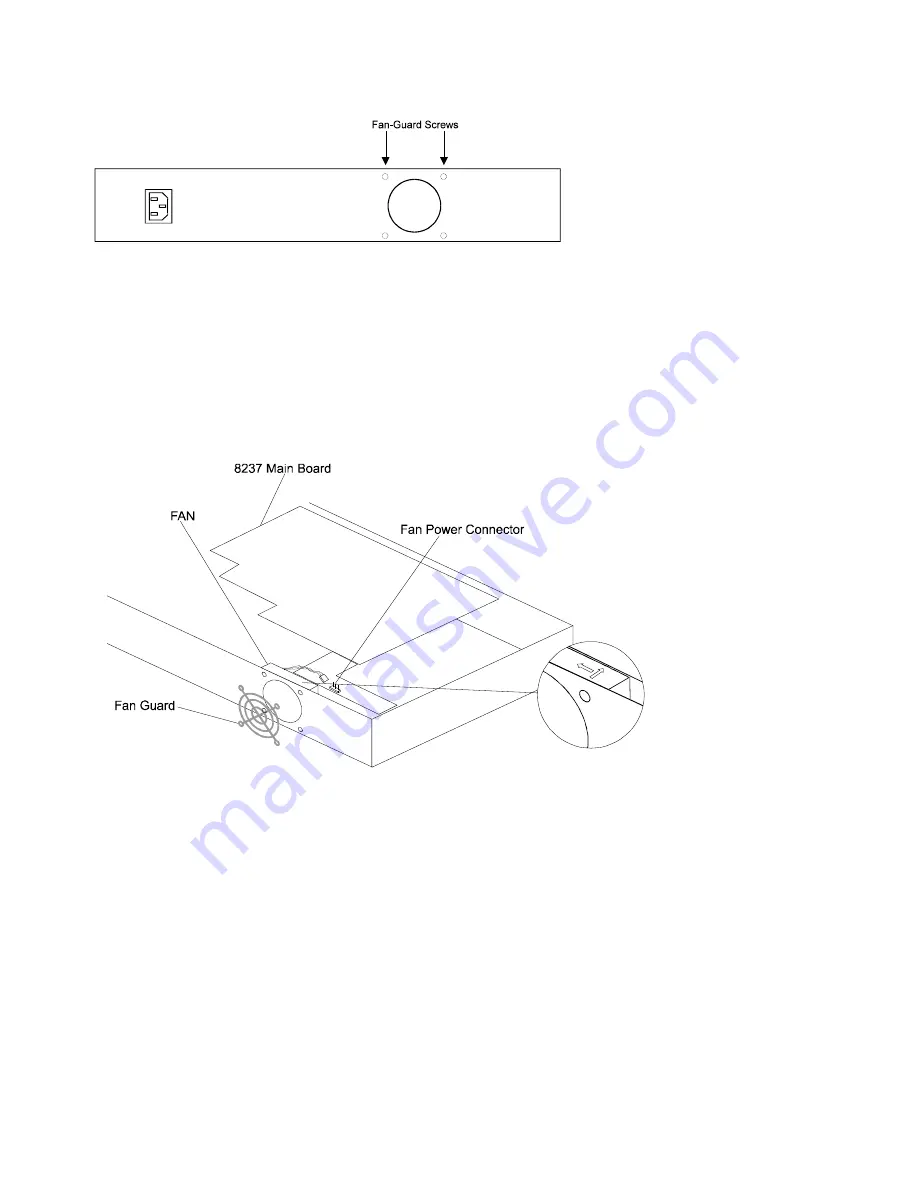
Figure 4-18. 8237 Back View
c. Grasp the top cover of the 8237 at the rear of the machine and lift it
approximately 25 mm (1 in.) at the back. Then, slide the cover up and to the
rear to remove it.
Remove the top cover and set it aside.
3
Disconnect the three-wire fan power cable from its position on the main board.
4
Remove the two bottom screws that hold the fan and the fan guard to the 8237.
These are indicated in Figure 4-19. Retain the fan guard.
Figure 4-19. Fan Replacement
5
Set the new fan in the 8237. The arrows on the fan go as shown in Figure 4-19.
6
Replace the fan guard and the two fan-mounting screws removed in step 4.
7
Connect the new fan’s power cable to the connector pins from which the old
fan’s power cable was removed. Note that the cable connector will snap back
into place in one direction only.
8
Replace the cover by reversing the actions in step 2. Note that both sides of the
top cover fit inside the edges of the bottom cover.
9
Connect ac power by attaching the power cable to the 8237 and then to the ac
outlet.
10
Verify that the fan is operational. The fan’s direction of airflow should be into the
unit.
Summary of Contents for 8237
Page 1: ......
Page 2: ......
Page 7: ...vi 8237 Hub Installation and Planning Guide...
Page 15: ...xiv 8237 Hub Installation and Planning Guide...
Page 41: ...2 8 8237 Hub Installation and Planning Guide...
Page 91: ...3 50 8237 Hub Installation and Planning Guide...
Page 109: ...4 18 8237 Hub Installation and Planning Guide Figure 4 20 8237 Field Replaceable Parts...
Page 113: ...4 22 8237 Hub Installation and Planning Guide...
Page 117: ...A 4 8237 Hub Installation and Planning Guide...
Page 147: ...B 30 8237 Hub Installation and Planning Guide...
Page 166: ...Part Number 85H8847 Printed in Taiwan 85H8847 GA27 4186 00...


