background image

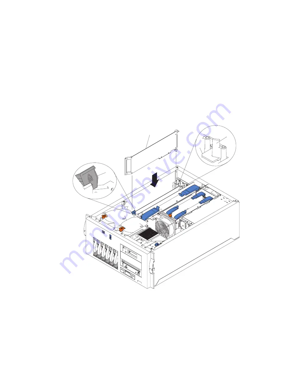
7. Refer to the documentation that was provided with the adapter for any cabling

instructions. It might be easier for you to route any cables before you install the
adapter.

8. If you are installing a long adapter, press on the touchpoint on the adapter retainer

flap (3) at the end of the slot nearest the front of the server, and rotate the adapter
retainer flap upward.

9. Remove the adapter from the antistatic package.

Attention: Avoid touching the components and gold-edge connectors on the

adapter.

10. Place the adapter, component-side up, on a flat, static-protective surface.

11. Set any jumpers or switches as described by the adapter manufacturer.

2

4

1

3

1

Adapter retention latch

2

Tab

3

Adapter retainer flap

4

Adapter

56

Installation Guide

Summary of Contents for 6C1

Page 1: ...pSeries 610 Model 6C1 and Model 6E1 Installation Guide SA38 0597 02 ERserver IBM ...

Page 2: ......

Page 3: ...pSeries 610 Model 6C1 and Model 6E1 Installation Guide SA38 0597 02 ERserver IBM ...

Page 4: ...s to Information Development Department H6DS 905 6C006 11400 Burnet Road Austin Texas 78758 3493 To send comments electronically use this commercial internet address aix6kpub austin ibm com Any information that you supply may be used without incurring any obligation to you International Business Machines Corporation 2001 2002 All rights reserved Note to U S Government Users Documentation related t...

Page 5: ...tep 8 Position the System Unit and Display 12 Step 9 Connect the Graphics Display 13 Step 10 Attach the Display Cable Toroid 14 Step 11 Connect the Keyboard and Mouse 15 Step 12 Connect the Serial and Parallel Devices 16 Step 13 Connect the Adapter Cables 17 Step 14 Connect the First External SCSI Device 18 Step 15 Connect Any Additional External SCSI Devices 19 Step 16 Are You Using the Rack Indi...

Page 6: ...a Processor Card 42 Removing a Processor Card 44 Installing a Memory Card 46 Removing a Memory Card 48 Installing Memory DIMMs 50 Removing Memory DIMMs 52 Installing Adapters 54 Removing Adapters 58 Installing Hot Swap Disk Drives 60 Removing Hot Swap Disk Drives 63 Installing an Internal Disk Drive 65 Installing a CD ROM Tape Drive DVD RAM or DVD ROM 66 Configuring or Deconfiguring Disk Drives 68...

Page 7: ...deral Communications Commission FCC Statement 102 European Union EU Statement 103 International Electrotechnical Commission IEC Statement 103 United Kingdom Telecommunications Safety Requirements 103 Avis de conformité aux normes du ministère des Communications du Canada 104 Canadian Department of Communications Compliance Statement 104 VCCI Statement 104 Radio Protection for Germany 104 Appendix ...

Page 8: ...Checking the Current Firmware Levels 119 Updating System Firmware 119 Index 121 vi Installation Guide ...

Page 9: ...hrough the unit must not be in direct contact with the rack v Care should be taken to ensure that a hazardous condition is not created due to uneven mechanical loading when installing this unit in a rack If the rack has a stabilizer it must be firmly attached before installing or removing this unit v Consideration should be given to the connection of the equipment to the supply circuit so that ove...

Page 10: ...ystem ensure that the power cables for those devices are unplugged before the signal cables are connected If possible disconnect all power cables from the existing system before you add a device Use one hand when possible to connect or disconnect signal cables to prevent a possible shock from touching two surfaces with different electrical potentials During an electrical storm do not connect cable...

Page 11: ...tion numbers and approval information CAUTION All IBM laser modules are designed so that there is never any human access to laser radiation above a class 1 level during normal operation user maintenance or prescribed service conditions Data processing environments can contain equipment transmitting on system links with laser modules that operate at greater than class 1 power levels For this reason...

Page 12: ...x Installation Guide ...

Page 13: ...ages or component failures must verify the accuracy of operations performed and data saved or transmitted by the system at or near the time of the outage or failure In addition users must establish procedures to ensure that there is independent data verification before relying on such data in sensitive or critical operations Users should periodically check the IBM support websites for updated info...

Page 14: ...xii Installation Guide ...

Page 15: ...lysis procedures MAPs error codes removal and replacement procedures and a parts catalog v The RS 6000 Eserver pSeries Diagnostic Information for Multiple Bus Systems order number SA38 0509 contains diagnostic information service request numbers SRNs and failing function codes FFCs v The RS 6000 Eserver pSeries Adapters Devices and Cable Information for Multiple Bus Systems order number SA38 0516 ...

Page 16: ...f work you do The Healthy Computing Web site gives ergonomic guidelines to help you understand the ergonomic considerations that you should know when working at a computer workstation The address is http www us pc ibm com healthycomputing Trademarks The following terms are trademarks of International Business Machines Corporation in the United States other countries or both v AIX v IBM v PowerPC v...

Page 17: ...and Model 6C1 h Books CD ROM other media h About Your Machine document h Power cables 2 standard 1 optional h 9 pin to 25 pin serial converters 2 optional hSCSI converter cable optional hASCII terminal optional hKeyboard optional Wrist palm rest optional hDisplay optional cable optional and cable toroid optional hMouse optional 1 ...

Page 18: ...D ANT PO WE R SUP PLY 1 2 3 A B 1 2 3 FAN TEM PER ATU RE Model E1 Model C1 Model 6C1 Rack Mount Only hRack Mounting Template h2 Rack Rails hCable Management Arm hRack Mounting Kit Envelope contains 8 rail screws 12 rack screws 24 cage nuts 12 for square holes and 12 for round holes 2 Installation Guide ...

Page 19: ...wer cables for the system unit and all attached devices are unplugged When adding or removing any additional devices to or from the system ensure that the power cables for those devices are unplugged before the signal cables are connected If possible disconnect all power cables from the existing system before you add a device Use one hand when possible to connect or disconnect signal cables to pre...

Page 20: ...with this step If you are installing a Model 6E1 Tower go to Step 7 Are All of the Internal Options Installed on page 12 You will need the following items v Rack Mounting Template v 2 Rack Rails v Cable Management Arm v Rack Mounting Kit Envelope v Screwdriver or Nutdriver 4 Installation Guide ...

Page 21: ...ectly Otherwise the installation cannot be completed successfully a Position the template on the front mounting rail aligning the holes b Install the cage nuts using the locations shown on the template c Move the template to the rear mounting rails d Install the cage nuts using the locations shown on the template Front View Rear View Rack Mounting Template Rack Mounting Template Chapter 1 Setting ...

Page 22: ...il front bracket to the front of the rack insert the front bracket pin into the hole above the cage nuts for the slide rail The two holes in the front bracket line up with the cage nuts 1 2 3 1 Left slide rail 2 Left rear 3 Left front c Do the same for the right slide rail d From the outside of the rack enclosure insert two M6 by 16 mm screws through each slide rail bracket and cage nut then tight...

Page 23: ... the cage nuts on the rear mounting rail b Insert two M6 by 16 mm screws to secure the mounting bracket to the rack 1 2 3 4 5 1 Right rear 2 Left rear 3 Right front 4 Left front 5 Hitch pin c Attach the free end of the cable management arm to the rear of the left slide rail using a hitch pin 5 Chapter 1 Setting Up the System 7 ...

Page 24: ... before installing or removing this unit 1 Mount the server on the slide rails a Extend the slide rails fully from the rack until the slide rails lock b Rest the blue wheel shaped knobs 1 on the slide rails at a point close to the rack c Lower the front of the server until the bottom notch in each chassis bracket fits into the top notch in the slide rail end 1 Slide the server backward or forward ...

Page 25: ...d Attach the rails to the sides of the server with M4 by 5 mm screws Chapter 1 Setting Up the System 9 ...

Page 26: ...3 Press the safety latches on the slide rails 1 and slide the server about halfway into the rack enclosure Note When the server is fully extended safety latches on the slide rails lock into place This action prevents the server from being accidentally pulled out too far and dropped To release the safety latch press in on the latch 1 10 Installation Guide ...

Page 27: ...lease the left and right slide latches and pull the server forward d Using a screwdriver tighten the screws that hold the front of the slide rails to the front of the rack e Slide the server into the rack enclosure again until the slide latches on the front chassis brackets click into place 5 Optional For additional security such as might be needed when transporting the rack fasten the server to t...

Page 28: ...play or ASCII terminal v Leave enough space around the system unit to safely and easily complete the setup procedures v Observe standard ergonomic guidelines while arranging your system unit so that you can work comfortably and safely For more information on arranging your workstation visit the Healthy Computing Web address at http www pc ibm com us healthycomputing v Be sure to maintain at least ...

Page 29: ...lay If you want to v Attach another display to your system unit OR v Change the default display resolution or refresh rate after completing the installation steps refer to the Customer Installable Options Library CD ROM for the documentation for your graphics adapter As shown in Step 10 Attach the Display Cable Toroid on page 14 connect the graphics display cable to the back of the display and to ...

Page 30: ...the Display Cable Toroid If the cable for your display does not include a toroid locate the toroid shipped with your system unit and follow the installation instructions included with the toroid 14 Installation Guide ...

Page 31: ...th an attached graphics display If a wrist palm rest was included with your keyboard and you want to attach it refer to the keyboard documentation for installation instructions As shown in the following figure connect the keyboard and mouse to the connectors on the rear of the system unit M K Chapter 1 Setting Up the System 15 ...

Page 32: ... have a remote ASCII terminal connect it through an external modem to serial connector S1 and connect a local ASCII terminal to serial connector S2 2 Connect any additional serial devices to the S3 connector 3 if it is not already in use If you have a parallel device such as a printer connect it to the parallel connector 4 4 1 2 3 3 1 2 4 5 16 Installation Guide ...

Page 33: ...ptional adapters such as token ring or 8 port EIA 232 connect the cables to the appropriate adapter connectors in the PCI slots of your machine Consult the About Your Machine document for the locations of installed adapters Chapter 1 Setting Up the System 17 ...

Page 34: ... 1 directly to the system unit 2 Connect the other end of the SCSI converter cable to one end of the SCSI device cable 2 3 Connect the other end of the SCSI device cable 3 to the SCSI device 4 Connect the SCSI device terminator 4 if this is the last device to be connected The last device on a SCSI bus must be terminated Note When a cable is not attached to the SCSI connector on the system unit the...

Page 35: ...t removed the SCSI bus terminator 3 Connect the other end of the SCSI cable 3 to the new SCSI device 4 Connect the SCSI bus terminator 4 5 Refer to the SCSI device documentation to set the SCSI device address For future reference you can record the address in Appendix D System Records on page 109 6 Repeat these steps for each additional external SCSI device you attach 3 1 2 4 Chapter 1 Setting Up ...

Page 36: ...stalled in a rack has a failure Ask your system administrator if you are unsure whether you are using the rack indicator feature If you are not using the rack indicator feature continue with Step 17 Are You Using an Ethernet Connection on page 21 Connect the rack indicator cable 20 Installation Guide ...

Page 37: ...tinue with Step 18 Connect the Power Cables to Server on page 22 To connect the Ethernet cable Note The twisted pair connector is compatible with the IEEE 802 3 Ethernet network 10 100 Base T link 1 Connect the twisted pair cable to either twisted pair connector 1 or 2 2 The twisted pair Ethernet cable is now installed Continue with Step 18 Connect the Power Cables to Server on page 22 1 1 2 2 Cha...

Page 38: ...o or from the system ensure that the power cables for those devices are unplugged before the signal cables are connected If possible disconnect all power cables from the existing system before you add a device Use one hand when possible to connect or disconnect signal cables to prevent a possible shock from touching two surfaces with different electrical potentials During an electrical storm do no...

Page 39: ...Plug the power cables into the power supply connectors 2 and route the power cables 1 through the cable restraint bracket 3 1 3 3 2 2 Chapter 1 Setting Up the System 23 ...

Page 40: ...20 Connect the Power Cables to Electrical Outlets on page 25 1 Route the power cords mouse cable and keyboard cable through the cable restraint bracket 2 Route all cables through the cable management arm attaching the cables to the arm with the hook and loop fastener strips provided The wraps are provided for additional cable management 24 Installation Guide ...

Page 41: ...owing occurs v The operator panel displays OK and the green power LED 1 blinks When this occurs your system is in standby mode The following figure shows the operator panel in standby mode 1 2 OK 1 Power On LED 2 Operator Panel Display If your system does not stop in standby mode check all cables for good connection If you cannot find a problem call your support center for assistance Chapter 1 Set...

Page 42: ...ator panel v The fans in the system unit start spinning v The green power LED on the operator panel comes on solid v Checkpoint codes appear in the operator panel display 4 5 1 2 3 1 Power On Switch 2 Reset Switch 3 Operator Panel Display 4 Attention LED amber 5 Power On LED green v Follow the instructions on your display The AIX Documentation library is available at the following web address http...

Page 43: ...rinted versions of the books that are available in hardcopy go to http www ibm com shop publications order Operating System Documentation Documentation for the AIX operating system is available either from the AIX documentation CD or from the Web If you ordered the AIX documentation CD with your operating system you can access the information by loading the documentation CD onto a hard disk on you...

Page 44: ...28 Installation Guide ...

Page 45: ...AIX operating system get help if needed 2 Remove all tapes diskettes and CD ROM discs 3 Turn off the system unit power 4 Turn on the system unit power 5 After the keyboard POST indicator displays on the firmware console and before the last POST indicator speaker displays press the numeric 6 key on either the directly attached keyboard or the ASCII terminal to indicate that a service mode boot shou...

Page 46: ...und v The A Problem Was Detected On Time Stamp menu displays with either a service request number SRN or an error code Make a note of any codes displayed on the display or operator panel To perform additional system verification go to Step 4 Performing Additional System Verification To exit diagnostics go to Step 5 Stopping the Diagnostics on page 31 Step 4 Performing Additional System Verificatio...

Page 47: ...anged any attributes on your ASCII terminal to run the diagnostics change the settings back to normal 3 This completes the system verification If you received an error code record the code and report it to the service organization If the server passed all the diagnostic tests the verification process is complete and your server is ready to use Chapter 2 Verifying the Hardware Operation 31 ...

Page 48: ...32 Installation Guide ...

Page 49: ...an electrical shock Before installing or removing signal cables ensure that the power cables for the system unit and all attached devices are unplugged When adding or removing any additional devices to or from the system ensure that the power cables for those devices are unplugged before the signal cables are connected If possible disconnect all power cables from the existing system before you add...

Page 50: ... metal frame of the system unit at the same time v Handle the devices carefully to prevent permanent damage Stopping the System Unit Attention When shutting down your system to install options shut down all applications first and then shut down the operating system The system power turns off and the system goes into standby mode when the operating system is shut down Before removing power from the...

Page 51: ...ons inside the Model 6C1 you must put the server in the service position To place the server in the service position release the left and right side latches and pull the server toward the front until it is fully extended When the server is fully extended safety latches on the slide rails lock into place This prevents the server from being accidentally pulled out too far and dropped 1 After complet...

Page 52: ...Adapters see page 54 Removing Adapters see page 58 v Disk Drive Options Installing Hot Swap Disk Drives see page 60 Removing Hot Swap Disk Drives see page 63 v Installing a Internal Disk Drive see page 65 v Installing a CD ROM Drive Tape Drive DVD RAM or DVD ROM see page 66 v Configuring or Deconfiguring Disk and Media Drives see page 68 v Hot Swap Power Supplies Installing a Hot Swap Power Supply...

Page 53: ...rn off the server and all attached devices and disconnect all external cables and power cords 2 Slide the cover release lever 1 to the right to release the cover and slide the cover 2 toward the rear of the server about 25 mm 1 inch Move the top edge of the cover out from the server then lift the cover off the server Set the cover aside Attention For proper cooling and airflow replace the cover be...

Page 54: ...ne so place the server in the service position as described in Placing the Model 6C1 in the Service Position on page 35 3 Move the cover release lever 2 down while sliding the service access cover 1 toward the rear of the server about 25 mm 1 inch Lift the cover off the server and set the cover aside Attention For proper cooling and airflow replace the cover before turning on the server Operating ...

Page 55: ... BU S NON REDUNDANT POW ER SUPPLY 1 2 3 A B 1 2 3 FA N TE MPERAT URE 2 3 1 2 3 1 Bezel release lever 2 Bezel 3 Side with bezel tabs and slots 1 If you have not already done so remove the service access cover as described in Removing the Service Access Covers on page 37 2 Press the bezel release lever 1 and remove the bezel 2 Chapter 3 Installing Options in Your System 39 ...

Page 56: ...place the server in the service position as described in Placing the Model 6C1 in the Service Position on page 35 2 If you have not already done so remove the service access cover as described in Removing the Service Access Covers on page 37 3 Press the bezel release lever 1 and remove the bezel 2 40 Installation Guide ...

Page 57: ...odel 6C1 rack mount place the server in the service position as described in Placing the Model 6C1 in the Service Position on page 35 4 If you have not already done so remove the service access cover as described in Removing the Service Access Covers on page 37 5 Pull out on the snap button and remove the processor and memory card cover Snap Button Replacment Install the processor and memory card ...

Page 58: ...he service access cover as described in Removing the Service Access Covers on page 37 5 If you have not already done so remove the processor and memory card cover as described in Removing and Replacing Processor and Memory Card Cover on page 41 6 Remove the air flow baffle from the system 7 Remove the plastic boot from the processor card connector 8 Open the retention latches Both latches should b...

Page 59: ...es securing the card into the connector 11 If you have other options to install refer to Option List on page 36 If you do not have other options to install replace the processor and memory card cover as described in Removing and Replacing Processor and Memory Card Cover on page 41 12 Replace the system unit covers as described in Replacing the Service Access Covers on page 77 Chapter 3 Installing ...

Page 60: ...the service access cover as described in Removing the Service Access Covers on page 37 5 Remove the processor and memory card cover as described in Removing and Replacing Processor and Memory Card Cover on page 41 6 The processor card is secured in place with retention latches one on each end of the card Open the retention latches Attention To prevent damage to the card and the card connectors ope...

Page 61: ... processor and memory card cover as described in Removing and Replacing Processor and Memory Card Cover on page 41 9 Replace the system unit covers as described in Replacing the Service Access Covers on page 77 Chapter 3 Installing Options in Your System 45 ...

Page 62: ...ervice Position on page 35 4 If you have not already done so remove the service access cover as described in Removing the Service Access Covers on page 37 5 If you have not already done so remove the processor and memory card cover as described in Removing and Replacing Processor and Memory Card Cover on page 41 6 Open the retention latches Both latches should be in an upright position See the fol...

Page 63: ...If you have other options to install refer to Option List on page 36 If you do not have other options to install replace the processor and memory card cover as described in Removing and Replacing Processor and Memory Card Cover on page 41 10 Replace the system unit covers as described in Replacing the Service Access Covers on page 77 Chapter 3 Installing Options in Your System 47 ...

Page 64: ... the service access cover as described in Removing the Service Access Covers on page 37 5 Remove the processor and memory card cover as described in Removing and Replacing Processor and Memory Card Cover on page 41 6 The memory card is secured in place with retention latches one on each end of the card Open the retention latches Attention To prevent damage to the card and the card connectors open ...

Page 65: ... processor and memory card cover as described in Removing and Replacing Processor and Memory Card Cover on page 41 9 Replace the system unit covers as described in Replacing the Service Access Covers on page 77 Chapter 3 Installing Options in Your System 49 ...

Page 66: ... have not already done so remove the processor and memory card cover as described in Removing and Replacing Processor and Memory Card Cover on page 41 6 If you have not already done so remove the memory card as described in Removing a Memory Card on page 48 7 With one hand touch any metal surface of the chassis to minimize static electrical charges and then pick up the memory DIMM 8 Locate the mem...

Page 67: ... Card on page 46 for more information 12 If you have other options to install refer to Option List on page 36 If you do not have other options to install replace the processor and memory card cover as described in Removing and Replacing Processor and Memory Card Cover on page 41 13 Replace the system unit covers as described in Replacing the Service Access Covers on page 77 Chapter 3 Installing Op...

Page 68: ...ving the Service Access Covers on page 37 5 If you have not already done so remove the processor and memory card cover as described in Removing and Replacing Processor and Memory Card Cover on page 41 6 If you have not already done so remove the memory card as described in Removing a Memory Card on page 48 7 Locate the memory DIMM connectors and determine which DIMM you want to remove Slot J1 Slot...

Page 69: ...stalling a Memory Card on page 46 for more information 10 If you have other options to install refer to Option List on page 36 If you do not have other options to install replace the processor and memory card cover as described in Removing and Replacing Processor and Memory Card Cover on page 41 11 Replace the system unit covers as described in Replacing the Service Access Covers on page 77 Chapte...

Page 70: ...he server in the service position as described in Placing the Model 6C1 in the Service Position on page 35 4 If you have not already done so remove the service access cover as described in Removing the Service Access Covers on page 37 5 Determine which PCI adapter expansion slot you will use for the adapter Note Check the instructions that were provided with the adapter for any requirements or res...

Page 71: ...er guide over the tab on the top corner of adapter c Remove the expansion slot cover from the server 3 Store it in a safe place for future use Attention Expansion slot covers must be installed on all vacant slots This maintains the electromagnetic emissions characteristics of the system and ensures proper cooling of system components Chapter 3 Installing Options in Your System 55 ...

Page 72: ... the end of the slot nearest the front of the server and rotate the adapter retainer flap upward 9 Remove the adapter from the antistatic package Attention Avoid touching the components and gold edge connectors on the adapter 10 Place the adapter component side up on a flat static protective surface 11 Set any jumpers or switches as described by the adapter manufacturer 2 4 1 3 1 Adapter retention...

Page 73: ...r guide over the tab on the top corner of adapter Rotate the adapter retention latch 1 clockwise until it snaps into place Attention Power cannot be restored to the adapter slot if the tab is not lowered into place d Close the adapter retainer flap 3 if previously opened 13 Connect any needed cables to the adapter Attention Route cables so that the flow of air from the fans is not blocked 14 If yo...

Page 74: ...C1 in the Service Position on page 35 4 If you have not already done so remove the service access cover as described in Removing the Service Access Covers on page 37 5 Determine which adapter you are removing 6 Disconnect any cables attached to the adapter 4 1 2 3 1 Adapter retention latch 2 Tab 3 Adapter retainer flap 4 Adapter 7 If you are removing a long adapter press on the touchpoint on the a...

Page 75: ... it from the system board 11 If you are not installing another adapter in this slot install an expansion slot cover and close the adapter retainer flap 3 if previously opened 12 If you have other options to install refer to Option List on page 36 If you do not have other options to install replace the covers as described in Replacing the Service Access Covers on page 77 Chapter 3 Installing Option...

Page 76: ... only Note You do not have to turn off the server to install hot swap drives in these bays However you must turn off the server when performing any steps that involve installing or removing cables Refer to the following illustrations while you perform the steps in this procedure 1 1 Filler panel 60 Installation Guide ...

Page 77: ... server Attention Do not remove the drive from the tray assembly 3 Install the hard disk drive 2 in the hot swap bay a Ensure the drive tray handle 3 is open that is perpendicular to the drive b Align the drive tray assembly so that it engages the guide rails in the bay c Gently push the drive tray assembly into the bay until the drive connects to the backplane d Push the tray handle to the right ...

Page 78: ...uctions on the screen Successful configuration is indicated by the OK message displayed next to the Command field at the top of the screen 10 Press F10 to exit smitty 11 If you have other options to install refer to Option List on page 36 If you do not have other options to install close and lock the server door 62 Installation Guide ...

Page 79: ...e the drive from the hot swap bay until it has had time to spin down approximately 30 seconds Handle the drive carefully 3 Before you hot swap a drive make sure it is defective If you partially or completely remove a good drive instead of a defective one the server might lose valuable data Refer to the following illustration while you perform the steps in this procedure 2 3 2 Drive 3 Drive tray ha...

Page 80: ...st on the screen and press Enter 8 Follow the instructions on the screen to remove the drive 9 When you are asked Are you sure answer Yes and press Enter The power LED on the drive that you selected turns off 10 Remove the defective hard disk drive 2 by placing the handle 3 on the drive to the open position perpendicular to the drive and pulling the hot swap tray from the bay 11 Repeat the previou...

Page 81: ...the release levers 1 and pull the operator panel tray from the system unit 6 With one hand touch any metal surface of the chassis to minimize static electrical charges and then pick up the disk drive 7 Insert the disk drive into the operator panel tray 1 8 Align the screw holes on the disk drive with the screw holes on the operator panel tray 9 Install the four retaining screws 10 Install the oper...

Page 82: ... on page 35 4 Remove the bezel as described in Removing the Bezel on page 39 5 Remove the filler panel from the bay opening by pulling the filler panel away from the server You do not need the filler panel when you have a drive installed in the bay 6 Touch the static protective bag containing the drive to any unpainted metal surface on the server then remove the drive from the bag and place it on ...

Page 83: ...ap drive bays to the back of the drive 11 Connect a power cable to the back of the drive Power cables for non hot swap drives are preinstalled in the server The connectors are keyed and can be inserted only one way 12 If you have other options to install refer to Option List on page 36 If you do not have other options to install replace the bezel as described in Replacing the Bezel on page 75 Chap...

Page 84: ...om servers aix library Select Technical Publications This publication is also contained on the AIX Documentation CD The documentation is made accessible by loading the documentation CD files onto the hard disk or by mounting the CD in the CD ROM drive 9 Press F10 to exit smitty Deconfiguring Drives 1 Log in as root user 2 At the command line type smitty 3 Select System Storage Manager Physical and...

Page 85: ...y installed the system continues to function if a single power supply fails Refer to the following illustration while performing the steps in this procedure 1 4 5 6 7 2 3 1 Power supply 2 Filler panel 3 Cable restraint bracket 4 Power cord connector 5 Handle on power supply in open position 6 AC power light 7 DC power light Chapter 3 Installing Options in Your System 69 ...

Page 86: ...oling 2 Install the power supply 1 in the bay a Place the handle 5 on the power supply in the open position that is perpendicular to the power supply and slide the power supply into the chassis b Gently close the handle to seat the power supply in the bay 3 Plug the power cord for the added power supply into the power cord connector 4 4 Route the power cord through the cable restraint bracket 3 5 ...

Page 87: ... following illustration while performing the steps in this procedure 1 4 5 6 7 2 3 1 Power supply 2 Filler panel 3 Cable restraint bracket 4 Power cord connector 5 Handle on power supply in open position 6 AC power light 7 DC power light Chapter 3 Installing Options in Your System 71 ...

Page 88: ...ng the power supply from the bay 3 If you are not replacing the power supply a Install a power supply filler panel 2 Note During normal operation each power supply bay must have either a power supply or filler panel installed for proper cooling b Open the cable restraint bracket 3 and remove the power cord from the cable restraint bracket Close the cable restraint bracket c Unplug the power cord f...

Page 89: ...The following illustration shows the replacement of a hot swap fan assembly Refer to this illustration while performing the steps in this procedure 1 2 3 4 5 6 7 8 9 10 11 12 1 Hot swap fan assembly 1 2 Fan assembly 1 LED 3 Fan 1 release button 4 Hot swap fan assembly 2 5 Fan assembly 2 LED 6 Fan 2 release button 7 Fan assembly 3 LED 8 Hot swap fan assembly 3 9 Fan 3 release latch 10 Fan assembly ...

Page 90: ...ated on the fan assemblies 4 If you are removing fan assembly 2 you must remove the processor and memory card cover See Removing and Replacing Processor and Memory Card Cover on page 41 5 If you are removing fan assembly 1 or fan assembly 2 pull out the snap button and remove the fan If you are removing fan assembly 3 or fan assembly 4 press the orange release latch 9 or 12 for the fan and pull th...

Page 91: ...eplacing the bezel check the serial number on the bezel with the serial number on the front of the system to ensure that you are installing the correct bezel on the correct system 1 Place the tabs at the bottom edge of the trim bezel 1 in the slots 2 at the bottom front of the server 2 Press the top of the bezel toward the server until the bezel clicks into place Chapter 3 Installing Options in Yo...

Page 92: ...he bezel with the serial number on the front of the system to ensure that you are installing the correct bezel on the correct system 1 Place the tabs on the left side of the trim bezel in the slots 3 at the left front of the server 2 Press the right end of the bezel toward the server until the bezel clicks into place 76 Installation Guide ...

Page 93: ... Slots 2 Service access cover 1 Align the left side cover 2 with the left side of the server about 25 mm 1 inch from the front of the server place the bottom of the left side cover on the bottom rail of the left side side of the chassis 2 Insert the tabs at the top of the cover into the slots 1 at the top of the server side 3 Hold the cover against the server and slide the cover toward the front o...

Page 94: ...es 1 Align the service access cover 1 with the top of the server about 25 mm 1 inch from the front of the server The flanges on the left and right sides of the cover should be on the outside of the server chassis 2 Hold the cover against the server and slide the cover toward the front of the server until the cover clicks into place 78 Installation Guide ...

Page 95: ...tions 1 If you have not already done so shut down the system as described in Stopping the System Unit on page 34 2 If you have not already done so unplug the system unit power cables from the electrical outlets 3 If your server is a Model 6C1 rack mount place the server in the service position as described in Placing the Model 6C1 in the Service Position on page 35 4 If you have not already done s...

Page 96: ...nto the battery mount Use your index finger to support the back of the battery mount during this operation 11 Replace any removed processor or memory cards 12 Replace the processor and memory card cover as described in Removing and Replacing Processor and Memory Card Cover on page 41 13 Replace the system unit covers as described in Replacing the Service Access Covers on page 77 14 Reset the time ...

Page 97: ...Connecting the Rack Indicator The rack indicator feature signals when a drawer installed in a rack has a failure Connect the rack indicator cable Chapter 3 Installing Options in Your System 81 ...

Page 98: ...82 Installation Guide ...

Page 99: ...ou identify the failing component go to the indicator panel see Indicator Panel on page 84 inside the server and check which LEDs are on If either of the following conditions exists v No LEDs lit on the indicator panel v PCI LED is the only LED lit on the indicator panel Go to Step 3 in Problem Determination Using the Standalone or Online Diagnostics on page 87 Otherwise continue with this procedu...

Page 100: ...oup of amber LEDs that indicate which functional area of the system is experiencing the fault such as power CPUs memory fans If one of these LEDs is on the user or service representative is directed to the physical area of the server where an additional LED will be on indicating the component that is responsible for the current fault Indicator Panel 84 Installation Guide ...

Page 101: ... LEDs AC Power Good and DC Power Good indicate the fault condition for the power supply Reporting the Problem After you have determined which component is failing report the problem 1 Record the following information before calling for service v Machine type and model v Server serial number v Any error codes that appear in the operator panel display or console v Any LEDs lit on the indicator panel...

Page 102: ... Log in as root user 3 At the command line type diag 4 Select Task Selection 5 Select Log Repair Action 6 Select the device that was repaired If the device is not listed select sysplanar0 7 Press F10 to exit diagnostics If the Attention LED remains on after you have completed the repair action and reset the LEDs call for service 86 Installation Guide ...

Page 103: ... to determine which field replaceable units FRUs are needed to restore the system to correct operation Step 1 Considerations before Running This Procedure Note See the operator manual for your ASCII terminal to find the key sequences you need to respond to the diagnostic programs v The diagnostics can use a display connected to the video port or an ASCII terminal attached to a serial port v This p...

Page 104: ...to shut down your system 1 At the system prompt stop the operating system using the appropriate command for your operating system 2 After the operating system is stopped turn off the system unit 3 3 Go to Step 7 on page 89 Step 6 This step invokes the Online Diagnostics in concurrent mode 1 Log in as root user 2 Enter the diag command 3 Wait until the Diagnostic Operating Instructions are displaye...

Page 105: ... display problem NO Go to Step 8 YES Go to Step 10 on page 90 Step 8 Starting at the top of the following table find your symptom and follow the instructions given in the Action column Symptom Action Display problem Go to Step 9 All other symptoms Go to Problem Determination When Unable to Load Diagnostics on page 94 Step 9 Find your type of console display in the following table Then follow the i...

Page 106: ...ter key is within one horizontal row of keys Record error code M0KBD001 and report the problem to the service organization 102 key keyboard Identify by the type of Enter key used The Enter key extends into two horizontal rows of keys Record error code M0KBD002 and report the problem to the service organization Kanji keyboard Identify by the Japanese characters Record error code M0KBD003 and report...

Page 107: ...d Follow the displayed instructions until either the Diagnostic Mode Selection menu or an SRN is displayed If the Diagnostic Mode Selection menu is displayed select Problem Determination and go to Step 13 on page 92 If you get an SRN record it and go to Step 15 on page 92 The New Resource menu is displayed Follow the displayed instructions Note Devices attached to serial ports S1 or S2 do not appe...

Page 108: ...on the resources you are having problems with or select the All Resources option to check all of the configured resources Find the response in the following table and follow the instructions given in the Action column Diagnostic Response Action An SRN is displayed Go to Step 15 The system hangs Report SRN 109 200 The Testing Complete menu and the No trouble was found message displays and you have ...

Page 109: ...s the Standalone Diagnostics If you are unable to load the diagnostics go to Step 8 on page 89 1 Turn on the power 2 Insert the diagnostic CD ROM into the CD ROM drive 3 When the keyboard indicator displays press F5 on the directly attached keyboard or 5 on the ASCII keyboard to indicate that standalone diagnostics are to be loaded 4 Enter any requested passwords 5 Follow any instructions to selec...

Page 110: ...p 2 Step 2 Are the Online Diagnostics installed on this system NO Go to Step 4 on page 95 YES Go to Step 3 Step 3 This step attempts to load Online Diagnostics in service mode 1 Turn off the power 2 Turn on the power 3 If the keyboard indicator displays press F6 on the directly attached keyboard or 6 on the ASCII keyboard to indicate that online diagnostics are to be loaded 4 Enter any requested p...

Page 111: ...re that the room temperature is within 60 90 F If you do not find a problem record error code M0PS0000 and report the problem to the service organization The system appears to be stopped and NO beep was heard from the system unit Processor POST failure Report error code M0CPU000 The system appears to be stopped and NO beep was heard from the system unit E122 E123 or E124 is displayed on the operat...

Page 112: ...rt over at the beginning of this step If you are sure that you pressed the correct key in a timely manner go to Step 7 The system does not respond when the password is entered Go to Step 7 The system stopped and an indicator is displayed on the system console and an eight digit error code is not displayed If the indicator text or icon represents v A keyboard record error code M0KBD000 and report t...

Page 113: ...tep below 2 If you are attempting to load the Online Diagnostics try loading the Standalone Diagnostics Otherwise record error code M0SCSI01 and report the problem to the service organization The system appears to be stopped the disk activity light is on continuously and a beep was heard from the system unit Record error code M0MEM001 and report the problem to the service organization The system s...

Page 114: ...hin one horizontal row of keys Record error code M0KBD001 and report the problem to the service organization 102 key keyboard Identify by the type of Enter key used The Enter key extends into two horizontal rows of keys Record error code M0KBD002 and report the problem to the service organization Kanji keyboard Identify by the Japanese characters Record error code M0KBD003 and report the problem t...

Page 115: ... equipment Unauthorized changes or modifications could void the user s authority to operate the equipment This device complies with Part 15 of the FCC Rules Operation is subject to the following two conditions 1 this device may not cause harmful interference and 2 this device must accept any interference received including interference that may cause undesired operation European Union EU Statement...

Page 116: ...of the manufacturer s adapters it is essential that other optional cards not supplied by the manufacturer do not use main voltages or any other excessive voltages Seek advice from a competent engineer before installing other adapters not supplied by the manufacturer Avis de conformité aux normes du ministère des Communications du Canada Cet appareil numérique de la classe A respecte toutes les exi...

Page 117: ...ormitätserklärung ist die IBM Germany Dieses Gerät erfüllt die Bedingungen der EN 55022 Klasse A Für diese von Geräten gilt folgende Bestimmung nach dem EMVG Geräte dürfen an Orten für die sie nicht ausreichend entstört sind nur mit besonderer Genehmigung des Bundesministers für Post und Telekommunikation oder des Bundesamtes für Post und Telekommunikation betrieben werden Die Genehmigung wird ert...

Page 118: ...o correct the interference by one or more of the following measures v Reorient or relocate the receiving antenna v Increase the separation between the equipment and receiver v Connect the equipment into an outlet on a circuit different from that to which the receiver is connected v Consult an authorized dealer or service representative for help Properly shielded and grounded cables and connectors ...

Page 119: ...n against interference with licensed communication devices International Electrotechnical Commission IEC Statement This product has been designed and built to comply with IEC Standard 950 United Kingdom Telecommunications Safety Requirements This equipment is manufactured to the International Safety Standard EN60950 and as such is approved in the UK under the General Approval Number NS G 1234 J 10...

Page 120: ... Equipment and conforms to the standards set by the Voluntary Control Council for Interference by Information Technology Equipment VCCI This product is aimed to be used in a domestic environment When used near a radio or TV receiver it may become the cause of radio interference Read the instructions for correct handling Radio Protection for Germany Dieses Gerät ist berechtigt in Übereinstimmung mi...

Page 121: ...quipment For information on proper disposal of the batteries in this product please contact IBM at 1 800 426 4333 For information on disposal of sealed lead acid or nickel cadmium batteries outside the United States contact your local waste disposal or recycling facility Environmental Design The environmental efforts that have gone into the design of this system signify IBM s commitment to improve...

Page 122: ... A weighted sound pressure level at the 1 meter bystander positions for a random sample of machines 3 All measurements made in conformance with ISO 7779 and declared in conformance with ISO 9296 4 System Configurations v 7028 6E1 1 processor 2 hard files v 7028 6C1 2 processors 7 hard files 3 power supplies 106 Installation Guide ...

Page 123: ...ountry where such provisions are inconsistent with local law THIS MANUAL IS PROVIDED AS IS WITHOUT WARRANTY OF ANY KIND EITHER EXPRESSED OR IMPLIED INCLUDING BUT NOT LIMITED TO THE IMPLIED WARRANTIES OF NON INFRINGEMENT MERCHANTABILITY OR FITNESS FOR A PARTICULAR PURPOSE Some states do not allow disclaimer of express or implied warranties in certain transactions therefore this statement may not ap...

Page 124: ...108 Installation Guide ...

Page 125: ...formation Identification Numbers Record and retain the following information Product Name Eserver pSeries 610 Model 6C1 and Model 6E1 Serial Number Key Serial Number The system unit s serial numbers are located on the front of the machine as shown in the following illustration Serial Number 109 ...

Page 126: ...your system needs service Memory Card J16 J14 128MB 256MB 512MB 128MB 256MB 512MB 128MB 256MB 512MB J12 128MB 256MB 512MB J10 128MB 256MB 512MB J2 128MB 256MB 512MB J4 128MB 256MB 512MB J6 128MB 256MB 512MB J8 J15 J13 J11 J9 J1 128MB 256MB 512MB 128MB 256MB 512MB 128MB 256MB 512MB 128MB 256MB 512MB 128MB 256MB 512MB 128MB 256MB 512MB 128MB 256MB 512MB 128MB 256MB 512MB J3 J5 J7 110 Installation Gu...

Page 127: ... 2 ______________________________________________ Expansion Slot 1 ______________________________________________ Parallel Port ______________________________________________ Serial Port 1 ______________________________________________ Serial Port 2 ______________________________________________ Serial Port 3 ______________________________________________ External SCSI ____________________________...

Page 128: ... Panel 2 Bay D02 3 Bay D03 4 Disk Bay 1 5 Disk Bay 2 6 Disk Bay 3 7 Disk Bay 4 8 Disk Bay 5 9 Disk Bay 6 Note If you install a disk drive or other media device in your system record the definition in the drive definition field in the following table 112 Installation Guide ...

Page 129: ...Non SCSI CD ROM Drive SCSI Media Device Bay D03 2 __________________ Hot Plug Disk Bay 1 10 __________________ Hot Plug Disk Bay 2 11 __________________ Hot Plug Disk Bay 3 12 __________________ Hot Plug Disk Bay 4 13 __________________ Hot Plug Disk Bay 5 14 __________________ Hot Plug Disk Bay 6 15 __________________ Appendix D System Records 113 ...

Page 130: ...114 Installation Guide ...

Page 131: ...descriptions with those of your terminal and set your attributes accordingly Generated Code Set ASCII Screen Normal Normal Uses the EIA 232 interface protocol Row and Column 24 x 80 24 x 80 Uses the EIA 232 interface protocol Scroll Jump Jump Jump When the last character on the bottom line is entered the screen moves down one line Auto LF Off Off Off For the On setting pressing the Return key move...

Page 132: ...it when the Trace key is pressed Additional Communication Attributes The following communication attributes are for the 3151 3161 and 3164 terminals Communication Setup Attributes 3151 11 31 41 Settings 3151 51 61 Settings 3161 3164 Settings Description Operating mode Echo Echo Echo Data entered from the keyboard on the terminal is sent to the system unit for translation and then sent back to the ...

Page 133: ...terminal waits for 100 ms for the system unit to respond Additional Keyboard Attributes The following keyboard attributes are for the keyboard attached to the 3151 3161 and 3164 terminals Keyboard Setup Attributes 3151 11 31 41 Settings 3151 51 61 Settings 3161 3164 Settings Description Enter Return Return Return The Enter key functions as the Return key Return New line New line New line The curso...

Page 134: ...tings 3161 3164 Settings Description Line speed 9600 9600 9600 Uses 19200 or 9600 bps bits per second line speed to communicate with the system unit Word length bits 8 8 8 Selects eight bits as a data word length byte Parity Even Even No Stop bit 1 1 1 Places a bit after a data word byte Characters ALL ALL Line end CR LF Print View port Print EOL Off Print null Off 118 Installation Guide ...

Page 135: ... last five characters of the ROM level represent a date in a yyddd format where yy is the last two digits of the year and ddd is the Gregorian date of the firmware Check the Web site at http www rs6000 ibm com support micro for the latest level of downloadable firmware If the version of system firmware installed on your system is older than has an earlier date than the system firmware shown on the...

Page 136: ...nclude the periods in the commands shown above c AIX commands are case sensitive Type them exactly as shown You are asked by the system for confirmation to proceed with the firmware update and the required reboot If you confirm the system applies the new firmware reboots and returns to the AIX prompt This may take up to ten minutes depending on the configuration of the system Attention On some sys...

Page 137: ...7 removing 37 replacing 77 D deconfiguring disk drives 68 device records 110 internal and external options 110 internal files and devices 113 diagnostics loading 29 disk drives configuring 68 deconfiguring 68 documentation 27 hardware 27 operating system 27 documentation accessing 27 E electrical safety vii electrical vii laser compliance statement ix ergonomic information xiv Ethernet connecting ...

Page 138: ...removing continued adapters 58 bezel Model 6C1 40 bezel Model 6E1 39 hot swap power supply 71 memory card 48 memory DIMMs 52 processor and memory card cover 41 processor card 44 service access cover rack 38 service access cover tower 37 service access covers 37 static sensitive devices 34 repair action 86 replacing 77 battery 79 bezel Model 6C1 76 bezel Model 6E1 75 covers 77 hot swap disk drives ...

Page 139: ...W web sites ergonomic information xiv website 12 AIX operating system documentation 27 hardware documentation 27 healthy computing 12 printed publications 27 Index 123 ...

Page 140: ...124 Installation Guide ...

Page 141: ...k is Very Satisfied Satisfied Neutral Dissatisfied Very Dissatisfied Accurate h h h h h Complete h h h h h Easy to find h h h h h Easy to understand h h h h h Well organized h h h h h Applicable to your tasks h h h h h Please tell us how we can improve this book Thank you for your responses May we contact you h Yes h No When you send comments to IBM you grant IBM a nonexclusive right to use or dis...

Page 142: ...RESSEE Information Development Department H6DS 905 6C006 11400 Burnet Road Austin TX 78758 3493 _ _ _ _ _ _ _ _ _ _ _ _ _ _ _ _ _ _ _ _ _ _ _ _ _ _ _ _ _ _ _ _ _ _ _ _ _ _ _ _ _ _ _ _ _ _ _ _ _ _ _ _ _ _ _ _ _ _ _ _ _ _ _ _ _ _ _ _ _ _ _ _ _ _ _ _ _ _ _ _ _ _ _ _ _ _ _ _ _ _ _ _ _ _ _ _ _ _ _ _ _ _ _ _ _ _ _ _ _ _ _ _ _ _ _ _ _ _ _ _ _ _ _ _ _ _ _ _ _ _ _ _ _ _ _ _ _ _ _ _ _ _ _ _ _ _ _ _ _ _ _ _ ...

Page 143: ......

Page 144: ...IBMR Part Number 09P6110 Printed in the United States of America on recycled paper containing 10 recovered post consumer fiber February 2002 SA38 0597 02 1P P N 09P6110 ...

Reviews: