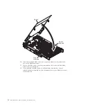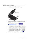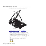
Note:
Make sure that the BladeCenter unit has the required number of power
modules present to supply power to the blade bay in which the expansion
blade is installed. For additional information, see the documentation that comes
with the BladeCenter unit.
3.
Turn on the blade server (see the documentation that comes with the blade
server for more information).
4.
If you installed the blade server in a BladeCenter unit that has a bezel, reinstall
the bezel assembly (see the documentation for your BladeCenter unit for
instructions).
Light path diagnostics
Use the light path diagnostics to troubleshoot your GPU expansion blade..
Light path diagnostics is a system of LEDs on the system board of the expansion
blade. When an error is indicated by the fault LED on the front of the expansion
blade, these LEDs inside the expansion blade can be lit to help identify the source
of the error. The fault LED on the blade device on which the expansion blade is
installed is also lit. If the blade device supports transfer of error and LED
information, fault-related information will be shown by the BladeCenter advanced
management module (see the
BladeCenter Advanced Management Module User's Guide
for additional information). If you cannot locate and correct a problem by using
the information in this section, see “Getting help and technical assistance,” on page
27 for more information.
To view the light path LEDs:
1.
Remove the combined blade server and expansion blades from the BladeCenter
unit (see “Removing a GPU Expansion Blade” on page 13).
2.
Place the expansion blade on a flat, static-protective surface.
3.
Remove the expansion blade cover and other expansion blades, if applicable, to
expose the expansion blade that has the lit fault LED (see “Removing the
expansion blade cover” on page 14).
4.
Press and hold the light path diagnostics switch for a maximum of 25 seconds.
The light path diagnostics (LP) LED will be lit to indicate that there is enough
power present to light the error LEDs, and LEDs indicating additional failure
information also will be lit.
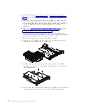
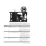
The following illustration shows the locations of the light path LEDs and the light
path diagnostics switch on the expansion blade system board.
22
BladeCenter GPU Expansion Blade: Installation Guide
Summary of Contents for 68Y7493
Page 1: ...BladeCenter GPU Expansion Blade Installation Guide ...
Page 2: ......
Page 3: ...BladeCenter GPU Expansion Blade Installation Guide ...
Page 6: ...iv BladeCenter GPU Expansion Blade Installation Guide ...
Page 16: ...xiv BladeCenter GPU Expansion Blade Installation Guide ...
Page 20: ...4 BladeCenter GPU Expansion Blade Installation Guide ...
Page 22: ...6 BladeCenter GPU Expansion Blade Installation Guide ...
Page 42: ...26 BladeCenter GPU Expansion Blade Installation Guide ...
Page 46: ...30 BladeCenter GPU Expansion Blade Installation Guide ...
Page 54: ...38 BladeCenter GPU Expansion Blade Installation Guide ...
Page 57: ......
Page 58: ... Part Number 90Y5467 Printed in USA 1P P N 90Y5467 ...

