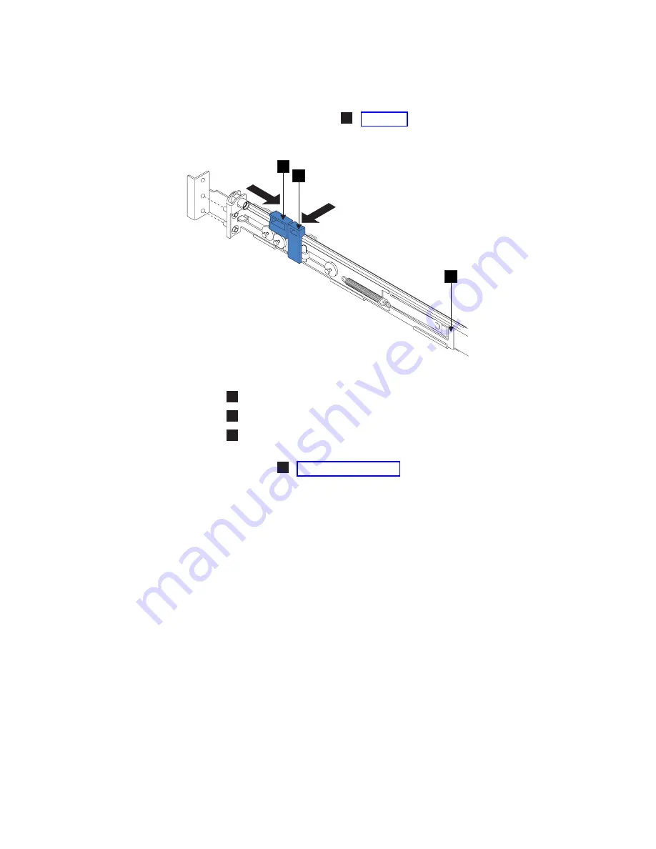
4.
Continue
to
slide
the
latch-lock
carrier
for
approximately
13
mm
(0.5
in).
The
latch-lever
engages
a
hole
in
the
back
bracket
assembly
and
holds
the
latch-lock
carrier
in
the
retracted
position.
5.
Push
the
back
rail
bracket
1
toward
the
front
of
the
rail
until
it
stops.
The
rail
is
now
at
its
shortest
adjustment.
1
Back
rail
bracket
2
Latch-lock
3
Latch-lever
6.
Place
the
front
end
of
the
left
rail
in
the
rack
cabinet.
Align
the
top
of
the
front
bracket
1
with
the
required
EIA
marking
that
is
on
the
rack.
2
1
3
Figure
62.
Opening
the
back
latch-lock
carrier
assembly
Appendix
A.
SAN
Volume
Controller
2145-8F4
and
SAN
Volume
Controller
2145-8F2
89
Summary of Contents for 2145UPS-1U
Page 2: ......
Page 8: ...vi IBM System Storage SAN Volume Controller Hardware Installation Guide...
Page 56: ...18 IBM System Storage SAN Volume Controller Hardware Installation Guide...
Page 72: ...34 IBM System Storage SAN Volume Controller Hardware Installation Guide...
Page 102: ...64 IBM System Storage SAN Volume Controller Hardware Installation Guide...
Page 138: ...100 IBM System Storage SAN Volume Controller Hardware Installation Guide...
Page 190: ...152 IBM System Storage SAN Volume Controller Hardware Installation Guide...
Page 192: ...154 IBM System Storage SAN Volume Controller Hardware Installation Guide...
Page 200: ...162 IBM System Storage SAN Volume Controller Hardware Installation Guide...
Page 228: ...190 IBM System Storage SAN Volume Controller Hardware Installation Guide...
Page 231: ......
Page 232: ...Part Number 31P1046 Printed in USA GC27 2132 01 1P P N 31P1046...


