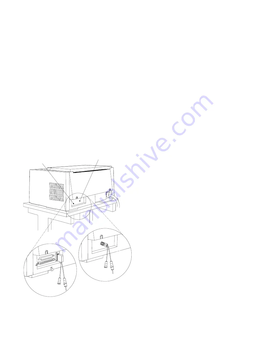
7. For Models 102 and 1I1: Align the two pins and the key slots in
the V-connector with the two holes and the key in the cable
connector on the bezel. Plug in the connector. Turn the
connector clockwise until it locks into place.
|
8. For Model 4I3: Insert the cable connector into the printer
|
connector on the bezel. Make sure the cable connector is
|
securely seated into place. Push and fasten the top and bottom
|
clips onto the cable connector.
C a b le C o n n e c to r
B e z e l
M o d e ls 4 I3
M od els 1 02 a nd 1 I1
2-8
User’s Guide
Summary of Contents for 102
Page 1: ...4230 Printer Models 102 1I1 202 2I1 4I3 and 5I3 User s Guide SA40 0564 04 ...
Page 2: ......
Page 3: ...4230 Printer Models 102 1I1 202 2I1 4I3 and 5I3 User s Guide SA40 0564 04 IBM ...
Page 10: ...viii User s Guide ...
Page 57: ...Chapter 1 Setting Up the 4230 Printer 1 35 ...
Page 71: ...The printer displays Bidirectional Adjustment Chapter 1 Setting Up the 4230 Printer 1 49 ...
Page 89: ...Chapter 1 Setting Up the 4230 Printer 1 67 ...
Page 133: ...The printer displays Bidirectional Adjustment Chapter 1 Setting Up the 4230 Printer 1 111 ...
Page 200: ...4 10 User s Guide ...
Page 211: ... Figure 5 2 Sample Printer Configuration Printout Model 4I3 Chapter 5 Tests 5 11 ...
Page 212: ... Figure 5 3 Sample Printer Configuration Printout Models 202 and 2I1 5 12 User s Guide ...
Page 213: ... Figure 5 4 Sample Printer Configuration Printout Model 5I3 Chapter 5 Tests 5 13 ...
Page 217: ...The printout should look similar to Chapter 5 Tests 5 17 ...
Page 220: ...The sample printout appears as follows 5 20 User s Guide ...
Page 222: ...5 22 User s Guide ...
Page 230: ...A 8 User s Guide ...
Page 278: ...B 48 User s Guide ...
Page 292: ...C 14 User s Guide ...
Page 294: ...D 2 User s Guide ...
Page 308: ...X 8 User s Guide ...
Page 319: ......
Page 320: ...IBM Part Number 1053301 Printed in U S A 1 533 1 SA4 564 4 ...


