background image

28

6.

 Operation:

 Mode

 Flow

 Chart

29

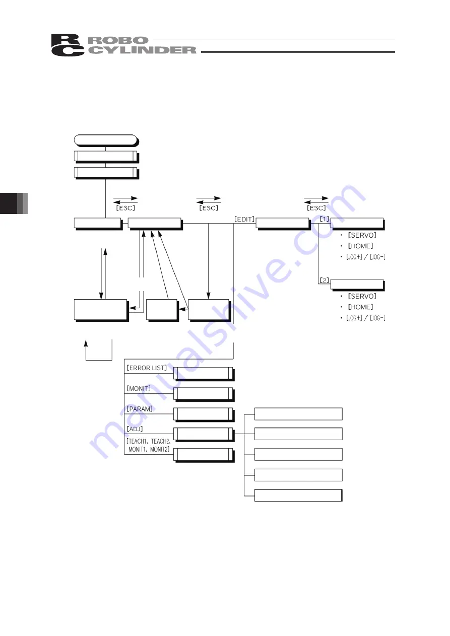
(2) Pulse Train (PCON-PL/PO, ACON-PL/PO and SCON: Pulse Train Mode)

The total picture of operations performed with the Teaching Pendant has the tree structure
as shown below.
To return to the previous screen, press the ESC key.

Power-ON

Set-up Communication

Select Axis

Operation

Start/End

Mode Select

Monitor

Error List

Jog

Return to “Set-up

Communication” when “2.

Reconnection” is selected

Return

1. End

* Before changing the parameter or leaving the

mode, check whether to reset software.

* Displayed only for PCON, ACON and SCON.

* Displayed only when

2 or more axes are

connected

User Parameter

TP Operation Mode

Return

* When the

servo is OFF

Servo OFF

Check

Soft

Reset

* When the

servo is ON

User Adjustment

TP operation mode

Homing

Axis No. Setting

Soft Reset

ErrList Clear

Sip Para

Press & hold

the STOP key

Press & hold

the STOP key

Jog/Inching

Inching

2. Reconnect

2. Reconnect

Summary of Contents for Robo Cylinder CON-T

Page 1: ...Teaching Pendant Instruction Manual Tenth Edition CON T CON TG CON TGS IAI Corporation ...

Page 2: ......

Page 3: ...of products and trademarks of each company shown in the sentences are registered trademarks Please Read Before Use Thank you for purchasing our product This Instruction Manual describes all necessary information items to operate this product safely such as the operation procedure structure and maintenance procedure Before the operation read this manual carefully and fully understand it to operate ...

Page 4: ......

Page 5: ...n Mode Note When the controller is set by connecting the Teaching Pendant to the PCON ACON controller without an AUTO MANU switch the conditions shown below occur When the controller is set by connecting the Teaching Pendant to the gateway unit SIO converter the conditions shown below occur If the Teaching Pendant is disconnected while the setting of TEACH 1 or TEACH 2 remains I O will become inva...

Page 6: ...put terminal is grounded the applicable teaching pendant model cannot be connected When it is connected the normal power is not supplied and it might cause the breakdown of the teaching pendant Applicable Models CON T RCM T RCM TD Teaching Pendant Controller 24VPower DO NOT CONNECT ...

Page 7: ... T Teaching Pendant also supports the RCP RCS E Con and RCP2 controllers 2 For the support for the ERC2 and ERC confirm it using the seal attached on the left side viewed from the rear of the cover Description on ERC2 Seal I O Type Unsupported Supported NP NP U5 M NP T1 4904 PN PN U3 M PN T1 4904 Description on ERC Seal I O Type Unsupported Supported NP T1 T1 4904 PN EP T1 EP T1 4904 Check the mode...

Page 8: ......

Page 9: ...gage the Teaching Pendant 20 5 3 Connection between CON TG TGS and the Controller 21 6 Operation Mode Flow Chart 27 1 Positioner PCON PL PO ACON PL PO and SCON Mode other than the Pulse Train Mode 27 2 Pulse Train PCON PL PO ACON PL PO and SCON Pulse Train Mode 28 6 1 Initial Screen and TP Operation Mode Screen During Power UP 29 6 2 Controller Selection when using multiple units 31 6 3 Operation ...

Page 10: ...e and Disable Setting 91 6 9 User Adjustment 92 6 9 1 Homing Operation Axis Number Setting Calibration and Time Setting 92 6 9 2 Software Reset 94 6 9 3 Error List Clear 95 6 10 TP Operation Mode 96 6 11 End 98 7 Message Area 99 7 1 Warning Label Error Code No 000h 07Fh 99 7 2 Teaching Pendant Message Level Error 100 7 3 Controller Error 100 Appendix Parameter Shipment Initialization Method 101 Te...

Page 11: ...the following environments 1 Location where there is any inflammable gas inflammable object or explosive 2 Place with potential exposure to radiation 3 Location with the ambient temperature or relative humidity exceeding the specification range 4 Location where radiant heat is added from direct sunlight or other large heat source 5 Location where condensation occurs due to abrupt temperature chang...

Page 12: ...the safety factor of the hook in such factors as shear strength Do not get on the load that is hung on a crane Do not leave a load hung up with a crane Do not stand under the load that is hung up with a crane 3 Storage and Preservation The storage and preservation environment conforms to the installation environment However especially give consideration to the prevention of condensation Store the ...

Page 13: ...s no disconnection or looseness Failure to do so may cause a fire electric shock or malfunction of the product Never cut and or reconnect the cables supplied with the product for the purpose of extending or shortening the cable length Failure to do so may cause the product to malfunction or cause fire 3 Grounding The grounding operation should be performed to prevent an electric shock or electrost...

Page 14: ... to secure safety Do not insert a finger or object in the openings in the product Failure to do so may cause an injury electric shock damage to the product or fire When releasing the brake on a vertically oriented actuator exercise precaution not to pinch your hand or damage the work parts with the actuator dropped by gravity 5 Teaching When the work is carried out with 2 or more persons make it c...

Page 15: ...inal block or any of the various setting switches in the power ON mode Failure to do so may result in an electric shock or malfunction 7 Automatic Operation Check before starting the automatic operation or rebooting after operation stop that there is nobody in the safety protection fence Before starting automatic operation make sure that all peripheral equipment is in an automatic operation ready ...

Page 16: ...sult in a damage to the product When releasing the brake on a vertically oriented actuator exercise precaution not to pinch your hand or damage the work parts with the actuator dropped by gravity The slider or rod may get misaligned OFF the stop position if the servo is turned OFF Be careful not to get injured or damaged due to an unnecessary operation Pay attention not to lose the cover or untigh...

Page 17: ...e product is not handled correctly will result in death or serious injury Danger Warning This indicates a potentially hazardous situation which if the product is not handled correctly could result in death or serious injury Warning Caution This indicates a potentially hazardous situation which if the product is not handled correctly may result in minor injury or property damage Caution Notice This...

Page 18: ... ...

Page 19: ...n easy to read location In addition give special consideration to prevent third parties from turning on the power carelessly by hauling in the power cord to the operator Alternatively lock the power plug or receptacle and direct the operator to keep the key or prepare a safety plug 4 When more than one operator works advance work by determining the signal method and checking each other s safety Es...

Page 20: ...a specification defect or problem or by the poor quality of our product Note that breakdowns due to any of the following reasons are excluded from the scope of warranty 1 Anything other than our product 2 Modification or repair performed by a party other than us unless we have approved such modification or repair 3 Anything that could not be easily predicted with the level of science and technolog...

Page 21: ...of safety Accordingly as a rule our product cannot be used in these applications Contact us if you must use our product for any of these applications 1 Medical equipment pertaining to maintenance or management of human life or health 2 A mechanism or mechanical equipment intended to move or transport people such as a vehicle railway facility or aviation facility 3 Important safety parts of mechani...

Page 22: ...Teaching Pendant Body so that the Teaching Pendant Cable does not get pulled by unwanted cables Caution This Teaching Pendant is designed exclusively for IAI RC Controllers PCON ACON SCON DCON ERC2 ERC3 RCP RCS E Con and RCP2 and should not be used to connect with other devices Turn the controller front side PORT switch OFF before connecting to controller equipped with a PORT switch ...

Page 23: ... to edit or display the data parameter data position data etc that is stored inside the controller as well as to execute teaching without using the PC Interface Software For using the CON TG TGS teaching pendant it is connected to the adaptor RCB LB TG TGS for the teaching pendant included to conform to the higher safety category Refer to 5 3 Connection of CON TG TGS to the Controller 4 1 Specifica...

Page 24: ...14 4 Functions and Specications of Teaching Pendant 4 2 External View External Dimensions ...

Page 25: ...ower supply to the motor will be cut off normally closed b contact For information on the emergency stop signal line and its status refer to the RC Robo Cylinder Operating Manual To reset the emergency stop status turn the operating portion of this switch in the arrow direction 1 LCD 23 Jog Jog key 4 EDIT mode select key 10 ESC key 11 PAGE UP PAGE DOWN key 15 ITEM BACK FWD key 2 EMERGENCY STOP 3 T...

Page 26: ...ters etc in the controller and commands of the actuator movement system SftyVel Non Enables movement at the speed registered in position data MONIT1 The LED is lit in the Monitor 1 mode PIO Prh Enables monitoring only Writing of position data parameters etc in the controller and commands of the actuator movement system are disabled SftyVel Efct Keeps the maximum speed at the safety speed set for t...

Page 27: ...ration retry operation after returning to the upper layer with the ESC key Input data cancel during data input operation If you press this key during data input operation the input data will be canceled Stop switch during movement or continuous movement Once this switch is pushed down during movement or continuous movement operation will decelerate and stop immediately 11 PAGE UP PAGE DOWN key Cha...

Page 28: ... for numeric input To input characters from A to F for the hexadecimal number perform the following operation Applicable for Version V1 10 or later A Hold key down and press key at the same time B Hold key down and press key at the same time C Hold key down and press key at the same time D Hold key down and press key at the same time E Hold key down and press key at the same time F Hold key down a...

Page 29: ...ed as follows 1st Stage Switch OFF The condition where finger is released from the switch or the force of pressing the switch is very weak 2nd Stage Switch ON Condition where the switch is pressed with appropriate force 3rd Stage Switch OFF Condition where the switch is pressed strongly The servo motor can be turned ON under the switch ON condition When the switch is turned OFF the driving power so...

Page 30: ...Pendant connector Caution In the case of using PCON ACON SCON or ERC2 when the teaching pendant is disconnected the controller is stopped momentarily in an emergency that the emergency stop is cancelled Do not disconnect the teaching pendant during the controller operation Also take the greatest care to design the emergency stop circuit including the emergency stop switch for the teaching pendant ...

Page 31: ...TG and RCB LB TG Caution When the teaching pendant CON TG is not to be connected make sure to insert the dummy plug DP 4 into the adaptor for the teaching pendant Controller Model Dummy Plug Teaching Pendant Controller Adaptor Connection Cable Adaptor for the Teaching Pendant Safety Circuit CON TG RCB LB TG DP 4 ...

Page 32: ...n the teaching pendant CON TGS is not to be connected make sure to insert the dummy plug DP 4S into the adaptor for the teaching pendant Controller Model Dummy Plug Teaching Pendant Controller Adaptor Connection Cable Adaptor for the Teaching Pendant Safety Circuit RCB LB TGS CON TGS DP 4S ...

Page 33: ... CON TG is not to be connected make sure to insert the dummy plug DP 4S into the adaptor for the teaching pendant Controller Model Dummy Plug Teaching Pendant Controller Adaptor Connection Cable Adaptor for the Teaching Pendant Safety Circuit RCB LB TGS DP 4S Connector Conversion Cable Set CB CVTG LBS002 CON TG ...

Page 34: ... Connector on the EMG side Connector on the ENB side Insert the connector with the wire arrangement that has been kept from the delivery time Adaptor for the Teaching Pendant Wiring Color Signal YW YW YW YW Wiring Color Signal YW YW YW YW Wire Arrangement of the Connector on the EMG side at the time of delivery Wire Arrangement of the Connector on the ENB side at the time of delivery Connection be...

Page 35: ...n the ENB side Insert the connector with the wire arrangement that has been kept from the delivery time Adaptor for the Teaching Pendant Wiring Color Signal YW YW YW YW Wiring Color Signal YW YW YW YW Wire Arrangement of the Connector on the EMG side at the time of delivery Wire Arrangement of the Connector on the ENB side at the time of delivery CON TGS RCB LB TGS 7 8 9 10 11 12 7 12 ...

Page 36: ...he connector with the wire arrangement that has been kept from the delivery time Adaptor for the Teaching Pendant Wiring Color Signal YW YW YW YW Wiring Color Signal YW YW YW YW Wire Arrangement of the Connector on the EMG side at the time of delivery Wire Arrangement of the Connector on the ENB side at the time of delivery CON TG RCB LB TGS Connector Conversion Cable Set CB CVTG LBS002 7 8 9 10 1...

Page 37: ...End Displayed only when 2 or more axes are connected Teach Play User Parameter Available only for PCON ACON SCON ERC2 TP Operation Mode Mode Select Mode Select When the servo is OFF Servo OFF Check Soft Reset When the servo is ON User Adjustment TP operation mode Homing Axis No Setting Soft Reset ErrList Clear Sip Para Press hold the STOP key Monitor Error List Before changing the parameter or lea...

Page 38: ...t Jog Return to Set up Communication when 2 Reconnection is selected Return 1 End Before changing the parameter or leaving the mode check whether to reset software Displayed only for PCON ACON and SCON Displayed only when 2 or more axes are connected User Parameter TP Operation Mode Return When the servo is OFF Servo OFF Check Soft Reset When the servo is ON User Adjustment TP operation mode Homin...

Page 39: ... to the Teaching Pendant and operation starts In the case of a controller with a PORT switch power will be supplied to the Teaching Pendant and operation will start once power is supplied to the Teaching Pendant Upon power on the LCD display screen hereinafter called the screen displays the Teaching Pendant software version as follows Initial Screen During Power UP ...

Page 40: ...he maximum speed at the safety speed set for the parameter regardless of position data TEACH2 The LED is lit in the Teach 2 mode PIO Prh Enables writing of position data parameters etc in the controller and commands of the actuator movement system SftyVel Non Enables movement at the speed registered in position data MONIT1 The LED is lit in the Monitor 1 mode PIO Prh Enables monitoring only Writin...

Page 41: ...t screen The controller can connect up to 16 units However the PCON ACON SCON DCON ERC2 or ERC3 group controllers cannot be used by linking to the RCP RCS E Con or RCP2 controllers Axis Selection Screen 1 Protocol type display M Modbus T proprietary protocol 2 Axis No display 3 Connection axis display In the case of PCON ACON SCON DCON ERC2 or ERC3 the series name and type name of the connection a...

Page 42: ...RC3 Mode other than the Pulse Train Mode Display and Edit function for positioner table Refer to 6 4 and 6 5 Pulse Train PCON PL PO ACON PL PO or SCON Pulse Train Mode ERC3 Pulse Train Mode Jog Operation Inching Operation Refer to 6 5 8 2 MONIT Controller status display Refer to 6 6 3 ERROR LIST 4 PARAM Setting of axis zone signal output range and axis attributes Refer to 6 8 5 ADJ Executing homin...

Page 43: ...yed A Absolute coordinate specification ABS I Relative coordinate specification INC Position and Velocity Data Screen Specification of Position No When the position No is incremented or decremented with the or key the position data of the displayed position No will be displayed in order Alternatively move the cursor to the position No with the or key input a numeric value with the ten keys and pre...

Page 44: ... the cursor in the screen will move Pressing the key again after the cursor has reached the top or bottom line will change the screen Press it several times Press it several times Press it several times Press it several times Press it several times Press it several times Press it several times Press it several times Press it several times Press it several times or return key or return key or retur...

Page 45: ...coordinate specification ABS I Relative coordinate specification INC Position and Velocity Data Screen Specification of Position No When the position No is incremented or decremented with the or key the position data of the displayed position No will be displayed in order Alternatively move the cursor to the position No with the or key input a numeric value with the ten keys and press the return k...

Page 46: ...cursor has reached the top or bottom line will change the screen In the same way when the return key is pressed the cursor in the screen will move Pressing the key again after the cursor has reached the top or bottom line will change the screen Press it several times Press it several times Press it several times Press it several times or return key or return key or return key or return key ...

Page 47: ...2 PIO pattern 3 ERC2 SE ERC3 PIO pattern 2 ERC3 PIO Converter PIO pattern 0 1 2 4 5 PCON C CG CF PIO pattern 0 1 2 4 5 CA PIO pattern 0 1 2 4 5 CY PIO pattern 1 SE ACON C CG PIO pattern 0 1 2 4 5 ACON CA PIO pattern 0 1 2 4 5 CY PIO pattern 1 SE DCON CA PIO pattern 0 1 2 4 5 SCON C positioner PIO pattern 0 1 2 4 5 SCON CA positioner PIO pattern 0 1 2 4 5 6 7 1 No Indicates the position data number...

Page 48: ...from being applied to the actuator in consideration of the installation conditions and the shape of transferred work by referring to the List of Actuator Specifications in the Appendix Increasing such values largely relates to the transfer mass and the actuator characteristics vary depending on the model consult IAI regarding the input limiting values 5 Push Select the positioning operation or push...

Page 49: ...oximity switch type of PCON CY and ACON CY 3 point type and proximity switch type Push operation It defines the maximum push amount from the target position in the push operation Set the positioning width in such a way as to prevent positioning completion before the actuator contacts work by considering mechanical variations of work Since increasing the positioning width value hastens the next seq...

Page 50: ... Movement command to backward end Movement command to forward end Movement command to midpoint It defines the acceleration deceleration characteristics The default value is 0 0 Trapezoid pattern 1 S shaped motion 2 First order delay filter Trapezoid pattern Set the acceleration and deceleration in the Acc and Dcl fields of the position table Setting example Home Zone output signal Backward end sid...

Page 51: ...eaching Pendant operation Note It cannot be set for the ERC2 or PCON controller The parameter No 56 is reserved First order delay filter More gradual acceleration deceleration curves are drawn than the linear acceleration deceleration trapezoid pattern Use this in the applications by giving micro vibrations to work during acceleration deceleration not desired Set the degree of the first order lag ...

Page 52: ...model load condition etc but the holding current decreases approximately by a factor of 2 to 4 No displacement occurs since this method maintains the servo ON status The actual holding current can be checked on the monitoring screen of PC compatible software Auto servo OFF method When a given length of time has elapsed after completion of positioning the servo OFF status is automatically entered S...

Page 53: ...to deal with 3 types of vibration There are 3 parameters corresponds to 1 type of vibration and they are compiled in 1 set Set the parameter set corresponds to the position number necessary for the vibration control in the position table Setting Vibration Control Frequency Specific Frequency Parameter No 0 Standard Position Control No Vibration Control 1 Vibration Control Parameter Set 1 97 to 100...

Page 54: ...ates are in the negative direction Caution In the case of PCON ACON or SCON there are cases where the input value to Push may be rounded off to the multiple of the minimum resolution of the controller during data acquisition from the controller 3 Vel Input the speed at which the actuator will be moved in mm sec The initial value will depend on the actuator type 4 Acc Dcc Input the acceleration dec...

Page 55: ...ould be placed in the range column Diagram A Diagram B 7 Acc only MAX Selects either the assigned acceleration or the maximum acceleration Inputs are either 1 or 0 The default value is set as 0 0 Assigned acceleration The value placed in 4 will be used as the actual acceleration value and deceleration value 1 Maximum acceleration This will automatically utilize the maximum acceleration matched to ...

Page 56: ...wever only the maximum speed will be gained if the maximum speed is slower than the specified speed 4 Inching Use the arrow key to incrementally move and match the desired location and read that location current position into the position table For the input example see page 62 If you press the arrow key once the actuator will move by a specified pitch 0 03 0 10 0 50 mm If you continue pressing the...

Page 57: ...Press the key 2 3 Press the key to select Jog 4 If the SV OFF servo OFF status is displayed on the screen press the key The servo will automatically be turned ON SV ON servo ON will be displayed on the screen 5 Press the key Homing will automatically be performed 6 Press the key twice to return to the Edit Teach screen Press the key to select Teach Play Caution Operating instructions are described...

Page 58: ... any unregistered data the display will show sign 4 Move the cursor to the Pos input position with the or key 5 Input here and then press the Return key In order to stop during numeric input press the key to cancel the input With the left operation by pressing immediately after inputting the status will return to the 6 During new position data registration the initial values set with the user para...

Page 59: ...ange to the screen of Position No 1 for Acc and Dcc 8 Change the screen to the screen for Pos and Vel with the key Move the cursor to Pos with the key 9 Move the cursor to the Pos input position with the or key Input here and then press the Return key In order to stop during numeric input press the key to cancel the input 10 The cursor will automatically move to the Vel input position ...

Page 60: ...ow Chart Operation Screen Reference 11 Input here and then press the Return key Press the key The cursor will automatically move to the next No 2 position The screen will change to the screen of Position No 2 for Acc and Dcc ...

Page 61: ... show sign 4 Move the cursor to the Pos input position with the or key 5 Input here and then press the Return key In order to stop during numeric input press the key to cancel the input Example by pressing immediately after inputting the status will return to the 6 During new position data registration the initial values set with the user parameters for Vel Acc Dcc etc will automatically be input ...

Page 62: ...ange to the screen of Position No 1 for Acc and Dcc 8 Change the display to the screen for Pos and Vel with the key Move the cursor to Pos with the key 9 Input here and then press the Return key 10 The cursor will automatically move to Vel 11 Change the display to the screen for Acc and Dcc with the key The screen will change 12 Change the display to the screen for Push LoTh and Range with the key...

Page 63: ...s the Return key Press the Return key again to move the cursor to Range For push control refer to the Controller Operating Manual 14 Input the maximum push range during push into the Range In this example input 5 mm Input and then press the Return key Press the key The screen will change to the screen of Position No 2 for Push LoTh and Range ...

Page 64: ...e the cursor to the Pos input position with the or key 5 Input here and then press the Return key In order to stop during numeric input press the key to cancel the input Example by pressing immediately after inputting the status will return to 6 During new position data registration the initial values set with the user parameters for Vel Acc Dcc etc will automatically be input In the left screen t...

Page 65: ...ange to the screen of Position No 1 for Acc and Dcc 8 Change the display to the screen for Pos and Vel with the key Move the cursor to Pos with the key 9 Input here and then press the Return key 10 The cursor will automatically move to Vel 11 Change the display to the screen for Acc and Dcc with the key The screen will change 12 Change the display to the screen for Push LoTh and Range with the key...

Page 66: ...screen will change 14 Change to the screen for Acc Dcl Mode and Incremental with the key Move the cursor to Incremental with the key 15 Set to Incremental relative coordinate specification Input and then press the Return key Press the key The screen will change to the screen of Postion No 2 for Cmnd Mode and Stop Mode ...

Page 67: ...t continuous loop Point A Point B speed 300mm sec Operation Screen Reference 1 Press the key 2 Press the key to select Teach Play 3 Press the key to select Jog Note Even if 2 Inching is selected the same direct teaching will be available 4 Press the key 5 Set the position No you want to input with the and key Press the key to put into the servo OFF status Any remaining data will be written over Fo...

Page 68: ...can change the position No you want to input with the and key 7 Press the key to select Yes 8 Press the Return key As for Vel Acc Dcc etc the initial value set with the user parameter will automatically be input Note If scan is performed without executing homing the error message Homing Incomplete will be displayed Return to the screen of 6 above with the ESC key to put into the servo ON status ke...

Page 69: ...t the position No youu want to input with the or key 12 Manually move the slider and match to the desired position Press the Return key 13 Press the key to select Yes 14 Press the Return key 15 Press the key 16 The screen will return to the Teach Play select screen ...

Page 70: ...tion in advance Refer to page 47 Increment specification Example 2 point continuous loop Point A Point B speed 300mm sec Operation Screen Reference 1 Press the key 2 Press the key to select Teach Play 3 Press the key to select Jog 4 Input the desired jog speed with the ten keys and press the Return key The input range is from 1 mm sec to the safety speed set for the parameter 5 Move the slider with...

Page 71: ...eturn key Any remaining data will be written over For any unregistered data the display will show sign 8 Press the key to select Yes 9 Press the Return key As for Vel Acc Dcc etc the initial value set with the user parameter will automatically be input 10 Press the key 11 The screen will return to the Teach Play select screen ...

Page 72: ...hing movement is performed first after power on it is required to perform home return operation in advance Refer to page 47 Increment specification Example 2 point continuous loop Point A Point B speed 300mm sec Operation Screen Reference 1 Press the key 2 Press the key to select Teach Play 3 Press the key to select Inching 4 Input the desired inching distance with the ten keys and press the Retur...

Page 73: ...eturn key Any remaining data will be written over For any unregistered data the display will show sign 8 Press the key to select Yes 9 Press the Return key As for Vel Acc Dcc etc the initial value set with the user parameter will automatically be input 10 Press the key 11 The screen will return to the Teach Play select screen ...

Page 74: ...al input the data entered will erase the old data The position will be updated only when the Return key is pressed to read in the current location direct teach jog increment It does not influence speed and others Once the position data is cleared the previous data will no longer remain anywhere Therefore when the next position data is registered any data other than position will be default values W...

Page 75: ...tion Screen Reference 1 Press the key 2 Press the key to select Clear 3 Set the position No you want to clear with the or key Press the Return key 4 Press the key to select Yes 5 Press the Return key 6 The data of the specified position No will be cleared Caution Operating instructions are described on the screens of PCON ACON SCON DCON ERC2 ERC3 ...

Page 76: ...ition data Operation Screen Reference 1 Press the key 2 Press the key to select All Clear 3 Press the key to select Yes 4 Press the Return key 5 All position data will be cleared Caution Operating instructions are described on the screens of PCON ACON SCON DCON ERC2 ERC3 ...

Page 77: ...number to the continuous position data number until an empty location is reached What is Continuous In the case of the position data similar to the table below when a Continuous command is executed from the position No the place where data exists continuously to the position before unregistered data will operate as one group No 3 Example Position No 2 No 1 No 2 and so on Posi Vel Acc Dcc In the ca...

Page 78: ...o perform home return operation in advance Increment specification 1 Move Operation Registered position data number assigned move Example Current position move towards position number 2 3 Operation Screen Reference 1 Press the key 2 Press the key to select Teach Play 3 Press the key to select Move 4 For any unregistered data the display will show sign 5 Set the position No you want to move with th...

Page 79: ...en PCON ACON or SCON is connected the maximum speed will be the safety speed set for the parameter if the MANU operation mode is set to the Teach mode 1 safety speed 7 If you press the key movement will be made to the location of the position No you set When the servo is not ON press the key to put into the servo ON status 8 When moving towards position of No 3 continuously Set 3 into the position...

Page 80: ...screen will return to the Teach Play select screen Caution When moving towards position in push mode After the actuator pushes the work and position complete output turns ON the actuator is in a state of continuously pressing the work Be extremely careful about handling at this time ...

Page 81: ... position numbers 1 to 3 Operation Screen Reference 1 Press the key 2 Press the key to select Teach Play 3 Press the key to select Cont 4 For any unregistered data the display will show sign 5 Set the position No you want to move first with the or key Press the Return key Caution Operating instructions are described on the screens of PCON ACON SCON DCON ERC2 ERC3 ...

Page 82: ...r ERC3 is connected the maximum speed will be the safety speed set for the parameter if the MANU operationmode is set to effective 7 If you press the key continuous movement will start The screen display will change to the screen of the position No currently moving When the servo is not ON press the key to put into the servo ON status 8 When stopping continuous operation press the or key When the ...

Page 83: ...73 6 Operation Mode Flow Chart Operation Screen Reference 9 When operation stops press the key 10 The screen will return to the Teach Play select screen ...

Page 84: ...any unregistered data the display will show sign 5 If you press the key in the servo ON status the status will change to the servo OFF 6 If you press the key in the servo OFF status the status will change to the servo ON Servo ON OFF can also be performed in the same way in 1 Jog 2 Inching or 4 Cont mode Caution Operating instructions are described on the screens of PCON ACON SCON DCON ERC2 ERC3 ...

Page 85: ...n be performed 1 Jog operation The Jog screen will be displayed If you press the key the cursor will move in the positive direction of the displayed coordinates If you press the key the cursor will move in the negativ e direction of the displayed coordinates Current position Indicates the current position The unit can be changed between mm and pulse with the or key Servo ON OFF If you press the ke...

Page 86: ...layed coordinates Current position Indicates the current position The unit can be changed between mm and pulse with the or key Servo ON OFF If you press the key the servo ON OFF status will be reversed Inching distance Input the desired inching distance with the ten keys and press the Return key The input range is from 0 01mm to 1 00mm set for the parameter Homing If you press the key homing will ...

Page 87: ... change to the special input port or version display screen The figure at the left shows an example of the PCON CY controller The display contents vary depending on the controller or controller s I O pattern For details refer to the operating manual of each controller If you press the or key the axis to monitor can be changed If you press the or key the screen will change To end monitoring press t...

Page 88: ...e version display screen On the input port screen if you press the key the screen will change to the output port monitor screen If you press the key the screen will change to the axis status screen On the output port screen if you press the key the screen will change to the input port monitor screen If you press the key the screen will change to the special input port monitor screen ...

Page 89: ... when an error occurs Displays the percent rated current in In the case of the PCON ACON SCON DCON ERC2 or ERC3 controller if you press the key the current value will be displayed in mA Display shown only for SCON CA In SCON CA Controller the status of Force Feedback Data and Calibration can be confirmed if a loadcell option is used Force Feedback Data This shows the force that is given as a feedb...

Page 90: ...isplayed The special input port screen will display special input ports such as HMCK home check sensor After this the screen will change to the special input port or version display screen If you press the or key the axis to monitor can be changed If you press the or key the screen will change To end monitoring press the key ...

Page 91: ...hange to the output port monitor screen If you press the key the screen will change to the version display screen If you press the key on the last screen of special input ports the version display screen will be displayed If you press the or key the axis to monitor can be changed To end monitoring press the key ...

Page 92: ... Total FAN driving time This shows the cumulative total of the driving time of the fan It is available only on controllers equipped with a fan The above values can be changed on the maintenance information editing screen Move the cursor to the number with using and keys Press the key Press WRT key next The number is changed M a i n t I n f o A 0 0 T o t a l M o v e d C o u n t 1 0 0 0 0 0 0 PAGE U...

Page 93: ...F Travelled distance threshold exceeded This alarm generates when the total travelled distance exceeds the threshold set in parameter No 148 Example of use for Total Drive Distance Times For an instance it is recommended to have a grease supply on the scraper area every 300km in the regular inspections when the drive distance exceeds 300km within 3 months for RCPW Rod Type Actuator Have a supply e...

Page 94: ...een applied to the controller No error has occurred If you press one of the or keys the mode will change to the mode of the pressed key Errors occurring in the controller will be displayed If you press the or key the Error List screens can be changed Alarm detailed code In the case of 0 will be displayed On the screen where the error description is displayed if you press the key Address and Time w...

Page 95: ...rectly inputting a numeric value of theparameter No with the ten key and pressing the Return key When changinga parameter move the cursor to the parameter value with the or key or Return key Input a numeric value with the ten key and press the Return key Press the key The screen will change to the next screen Press the key When 1 Yes is selected for Is the writing data written the screen will chan...

Page 96: ... same time On the following page user parameter display examples of the PCON CY controller are provided The contents will vary depending on each controller Refer to the operating manual of each controller Models which support the software reset restart are PCON ACON SCON DCON ERC2 For any model which does not support the software reset restore the power to the controller When the servo is ON the s...

Page 97: ...87 6 Operation Mode Flow Chart Examples of PCON CY Controller On following page ...

Page 98: ...88 6 Operation Mode Flow Chart From previous page On following page ...

Page 99: ...89 6 Operation Mode Flow Chart From previous page On following page ...

Page 100: ...90 6 Operation Mode Flow Chart From previous page ...

Page 101: ...software reset function Although pressing the emergency switch or port switch ON OFF will rewrite the parameter there may be ones that will not be changed Regarding parameter please refer to the Controller Operating Manual 1 Pause Pause input can be enabled or disabled with user parameter No 15 0 Enb 1 Dsb 2 Servo ON input Servo ON input can be enabled or disabled with user parameter No 21 0 Enb 1...

Page 102: ...d other controllers for which the axis number is set with the rotary switch on the front panel of the controller axis number setting is not available Perform the loadcell calibration SCON CA Move to the clock setting window to set the current time SCON CA PCON CA and ERC3 PIO Converter v Calibration Enter 6 to Adjustment No and press the Return key to perform a calibration Setting is available onl...

Page 103: ...s either or and the cursor switches in the following order year month day hour minute second year Press either or and the cursor switches in the back order second minute hour day month year second Move the cursor to where a change is desired 2 Press to increase the number Press to decrease the number Adjust the clock to the current time 3 Press the Return key to complete the time setting Press key...

Page 104: ...eset screen Press the key and press the Return key When not resetting software press the key and press the Return key The screen will return to the Mode Select screen When the servo is ON the screen will change to the Servo OFF confirmation screen Press the key and press the Return key Then the controller will restart and the screen will change to the Mode Select screen Since the servo is automatic...

Page 105: ...RC2 and ERC3 Input into Adjust No and press the Return key The screen will change to the Error List Clr screen Press the key and press the Return key The error list will be cleared and the screen will return to the Mode Select screen When not clearing the error list press the key and press the Return key The screen will return to the Mode Select screen ...

Page 106: ...of the mode you want to change from among the and keys As an example when changing from the TEACH1 mode status to the TEACH2 mode press key The screen will change to the TP Ope Mode Change data writing confirmation screen If you press the key and press the Return key the TP mode will change and the screen will change to the Mode Select screen The LED of TEACH2 which is the TP operation mode displa...

Page 107: ...and commands of the actuator movement system SftyVel Non Enables movement at the speed registered in position data Monitor 1 The LED is lit in the MONIT1 mode PIO Per Enables monitoring only Writing of position data parameters etc in the controller and commands of the actuator movement system are disabled SftyVel Efct Keeps the maximum speed at the safety speed set for the parameter regardless of ...

Page 108: ...m the initial screen Caution When multiple axes are connected with a controller link cable after recycling power of a controller that is not directly connected to the Teaching Pendant please execute a reconnect Caution TP Operation Mode When the controller is set by connecting the Teaching Pendant to the gateway unit SIO converter the conditions shown below occur If the Teaching Pendant is disconn...

Page 109: ...y Warning is probably due to the following possibilities RS485 communication abnormality Teaching Pendant operational mistake a RS 485 communication related abnormality Indicates occurrence of any abnormality on the RS485 communication line Code No 05Ah 05Bh 05Dh 05Eh 07Fh etc Communication error detected by the controller Cause 1 Teaching Pendant is in conflict with other devices PLC or PC For ex...

Page 110: ...oller operating manual carefully for error compliance If any errors of the below code numbers occur it is required to perform the error reset of the controller press the key to reset it in the case of a movement release level error It is required to perform the reset of the controller software in the case of a cold start level error Refer to 6 9 2 With regard to the controllers not equipped with t...

Page 111: ...n confirmation screen Press the key and press the Return key When not performing parameter initialization press the key and press the Return key The screen will return to the Mode Select screen The screen will change to the Software Reset screen Press the key and press the Return key When the servo is ON the screen will change to the Servo OFF confirmation screen Press the key and press the return...

Page 112: ...to the actuator specifications or parameter table and reenter a correct value 115 Homing Incomplete The current position was written when home return was not yet completed Execute home return again 117 No Move Data Target position is not set under the selected position number Enter the target position first 11E Pair Data Mismatch The values indicating the magnitude relationship of a pair of data a...

Page 113: ...was reached 220 Write in AUTO prohibited This messages indicates that parameter writing operation was performed in the AUTO mode of the PCON C CG ACON C CG or SCON controller 221 Write in Monitor mode prohibited This message indicates that position data or parameter writing operation was performed in the Monitor mode 222 Operation in AUTO prohibited This message indicates that actuator movement op...

Page 114: ...S switch settings are duplicated by mistake when multiple connectors are linked Action 1 Check if the RDY lamp on the controller is lit If the lamp is not lit the controller is faulty 2 If a spare Teaching Pendant is available replace the current pendant with the spare unit or with a PC and see if the message disappears 3 Supply power after connecting the link cable between the converter and contr...

Page 115: ...or List Screen Added Page 80 Addition of How to Input A to F for Hexadecimal Number Page 86 Calibration and Time Setting added to User Adjustment Page 87 Method for Time Setting Added Page 97 Content of 20A added and 20C 20D 210 and 211 deleted in Teaching Pendant Error Display Fifth edition Page 1 Contents added and changed in Safety Guide Page 43 Correction made in contents of operation in Secti...

Page 116: ...ate Revision Description 2019 05 Tenth edition Page 23 and 26 Correction made to model code for connector conversion cable set for connection to CON TG and RCB LB TGS Page 22 to 26 Descriptions revised regarding TP adapter Appendix ...

Page 117: ......

Page 118: ...INESS CENTER A8 303 808 Hongqiao Rd Shanghai 200030 China TEL 021 6448 4753 FAX 021 6448 3992 website www iai robot com Technical Support available in USA Europe and China Head Office 2690 W 237th Street Torrance CA 90505 TEL 310 891 6015 FAX 310 891 0815 Chicago Office 110 East State Parkway Schaumburg IL 60173 TEL 847 908 1400 FAX 847 908 1399 TEL 678 354 9470 FAX 678 354 9471 website www intell...

Reviews: