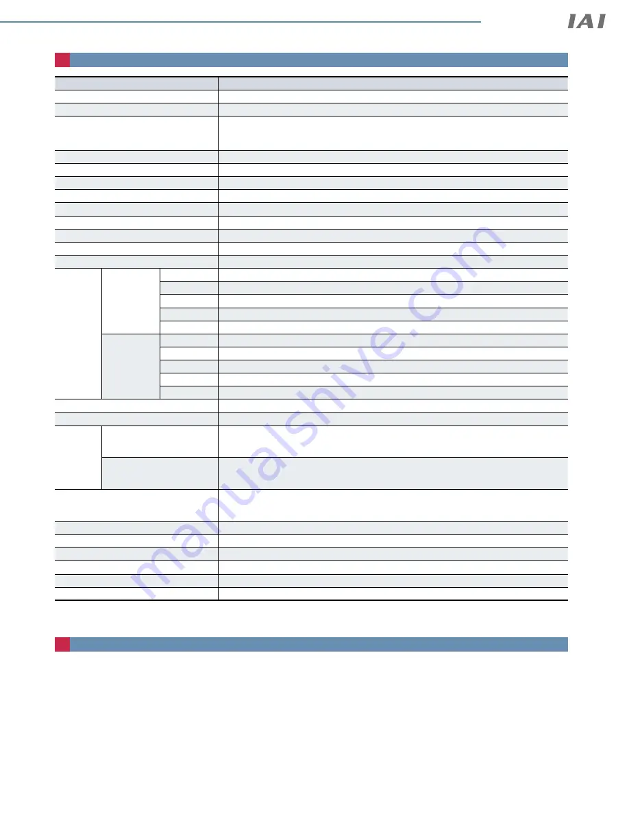
Basic Controller Specifications
Specification item
Specification content
Number of controlled axes
1 axis
Power supply voltage
24VDC ±10%
Power capacity(
including 0.3A control power)
(Note 1)
With energy-saving setting disabled: Rated 3.5A, max. 4.2A
With energy-saving setting enabled: Max. 2.2A
Brake release power supply
24VDC ±10%, 200mA (only for external brake release)
Generated heat (at 100% duty)
8W
Inrush current (Note 2)
8.3A (with inrush current limit circuit)
Momentary power failure resistance
Max 500µs
Motor size
£
35,
£
42
Motor rated current
1.2A
Motor control system
Weak field-magnet vector control
Supported encoders
Incremental (800 pulse/rev), battery-less absolute encoder (800 pulse/rev)
SIO
RS485 1ch (Modbus protocol compliant)
PIO
Input
specification
No. of inputs
3 points (forward, backward, alarm clear)
Input voltage
24VDC ±10%
Input current
5mA per circuit
Leakage current Max. 1mA per point
Isolation method Non-isolated
Output
specification
No. of outputs 3 points (forward complete, backward complete, alarm)
Output voltage 24VDC ±10%
Output current 50mA per point
Residual voltage 2V or less
Isolation method Non-isolated
Data setting, input method
PC teaching software, touch panel teaching pendant, digital speed controller
Data retention memory
Position and parameters are saved in non-volatile memory (no limit to number of rewrites)
LED
display
Controller status display
Servo ON (green light ON) / Alarm (red light ON) / Initializing when power comes ON (orange light
ON) / Minor failure alarm (green/red alternately blinking) / Operation from teaching: Stop from
teaching (red light ON) / Servo OFF (light OFF)
Wireless status display
Initializing wireless hardware, without wireless connection, or connecting from TP board (light OFF)
Connecting through wireless (green blinking) / Wireless hardware error (red blinking) / Initializing
when power comes ON (orange light ON)
Predictive maintenance/preventative
maintenance
When the number of movements or operation distance has exceeded the set value and when the
LED (right side) blinks alternately green and red at overload warning
*Only when configured in advance
Ambient operating temperature
0 ~ 40°C
Ambient operating humidity
5%RH - 85% RH or less (Non-condensing or freezing)
Operating environment
No corrosive gas and excessive dust
Insulation resistance
500 VDC 10MΩ
Electric shock protection mechanism
Class 1 basic insulation
Cooling method
Natural air cooling
(Note 1) In case of the RCON-EC, subtract 0.3A of control power from the control power.
(Note 2) Inrush current flows approx. 5ms after the power is turned on. (at 40°C) Inrush current value varies depending on the impedance of the power source line.
Solenoid valve method
ELECYLINDER® products normally use a double solenoid method.
Change parameter No. 9 ("solenoid valve type selection") to use the single solenoid method.
<Caution>
Operation cannot be performed using the single solenoid method when operating connected to RCON-EC.
Controller
30
EC
ELECYLINDER
®


