


Hardware Manual
BMS Master 4 / 4.5
Ref.: IR14417 A 15.01.2018
Page 47/76
6
Shield
5
BUS-A
4
BUS-B
3
5V-NET
2
NETGND
1
FAIL
The resistor values are adapted on the voltage range of the cell voltages. Thus an
optimum between maximum balance current and maximum board temperature is reached.
All resistor connection points rsp. all cell connection point are led to a 22-pole MicroFit-
connector, to give the possibility for balancing currents of up to 500 mA using an external
balancing resistor board or even only one resistor near every cell.
3.5.4.6
S
ERIAL
RS
485
I
NTERFACE AND
ERROR
S
IGNALLING
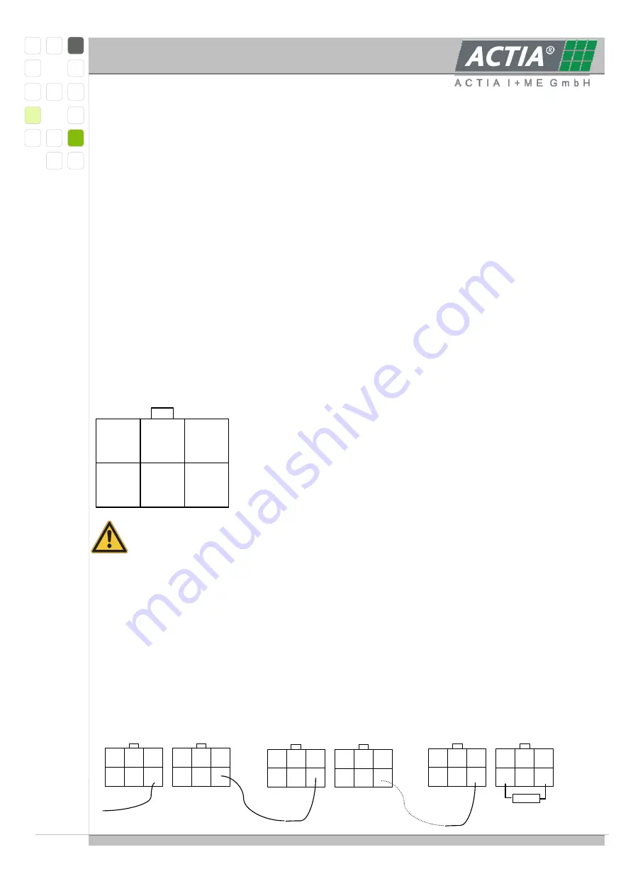
The RS485-interface is optical isolated with air and creeping distances of 10 mm at least.
The interface is supplied by the master with 5 VDC. The electrical reference point of the
interface is line NETGND.
The interface is ESD-protected up to 15 kV (human body model).
Pin assignment with view on the cable side of the connectors; the assignment is for both
connectors identical. With several slave modules in a system only one slave will be
connected directly to the master module, the remaining slave modules are connected one
to the next.
The pin assignment nomenclature corresponds to that of the
BMS MASTER.
Due to the dual connector layout each wire may be crimped
separately. The wire gauge must correspond with the selected
crimp contact.
When the distances are longer than a few centimeters it is strictly recommended to
use shielded twisted-pair-cable e.g. LiYY 3x2tp.
The FAIL-interface is optically isolated and realized as open-collector-output referenced to
NETGND. The output may sink approximately 2mA.
The slave modules have to be connected in chain, all open-collector-outputs paralleled in
OR-function. At the end of the slave chain the interface has to be terminated with a
resistor of 4.7 kΩ or 5.1 kΩ to +5VNET.
Schematic sketch for FAIL-cabling (one MASTER and several SLAVE_5):
Slave 1
Slave 2
Slave n
__________________ ___________________ _________________
6
Shield
5
BUS-A
4
BUS-B
3
5V-NET
2
NETGND
1
FAIL
6
Shield
5
BUS-A
4
BUS-B
3
5V-NET
2
NETGND
1
FAIL
6
Shield
5
BUS-A
4
BUS-B
3
5V-NET
2
NETGND
1
FAIL
6
Shield
5
BUS-A
4
BUS-B
3
5V-NET
2
NETGND
1
FAIL
6
Shield
5
BUS-A
4
BUS-B
3
5V-NET
2
NETGND
1
FAIL
6
Shield
5
BUS-A
4
BUS-B
3
5V-NET
2
NETGND
1
FAIL
Summary of Contents for BMS Master 4
Page 73: ...Hardware Manual BMS Master 4 4 5 Ref IR14417 A 15 01 2018 Page 73 76 6 CERTIFICATES...
Page 74: ...Hardware Manual BMS Master 4 4 5 Ref IR14417 A 15 01 2018 Page 74 76...
Page 75: ...Hardware Manual BMS Master 4 4 5 Ref IR14417 A 15 01 2018 Page 75 76...
Page 76: ...Hardware Manual BMS Master 4 4 5 Ref IR14417 A 15 01 2018 Page 76 76...