


Hardware Manual
BMS Master 4 / 4.5
Ref.: IR14417 A 15.01.2018
Page 19/76
3.1.3.5
CAN
I
NTERFACE
1
&
3,
CONNECTOR
CN105
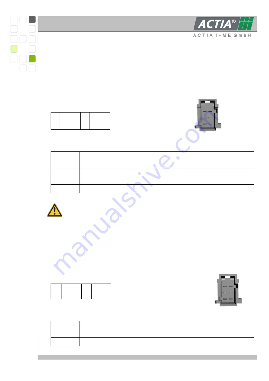
For the communication with other devices CAN interfaces are integrated according to CAN
specification V2.0B. Each CAN node is able to transmit and receive standard frames with
either 11-bit- or 29-bit-identifiers.
Interface CAN 1 is operated by the XC167 processor.
Interface CAN 3 is operated by the AT91 processor.
Connector pin assignment / View on the pins:
1
CAN1H
4
CAN3H
2
CAN1L
5
CAN3L
3
Shield
6
Shield
Nomenclature:
CAN1H,
CAN1L
Controller Area Network channel 1
For communication with external devices, e.g. host computer.
CAN3H,
CAN3L
Controller Area Network channel 3
for communication with battery control specific units
Shield
Shield connection
The use of shielded and twisted pair cable is strongly recommended.
The termination of CAN-Bus № 1 and № 3 has to be done externally.
3.1.3.6
S
LAVE
M
ODULE
C
OMMUNICATION
,
CONNECTOR
CN106
Slave C, Slave 5 module communication is done via an RS485 interface. The interface is
not optical isolated, optical isolation is implemented on the slave modules; communication
baud rate is 19200 Bd. Single cell voltages, temperature values and commands for bypass
resistors are communicated.
Connector pin assignment / View on the pins:
1
BUSA
4
BUSB
2
5VNET
5
FAIL
3
GND
6
Shield
Nomenclature:
5VNET
Slave communication supply 5 V +40/-5 %, 350 mA max.
GND
Ground
BUSA,
RS485 bus lines
1
2
3
4
5
6
1
2
3
4
5
6
Summary of Contents for BMS Master 4
Page 73: ...Hardware Manual BMS Master 4 4 5 Ref IR14417 A 15 01 2018 Page 73 76 6 CERTIFICATES...
Page 74: ...Hardware Manual BMS Master 4 4 5 Ref IR14417 A 15 01 2018 Page 74 76...
Page 75: ...Hardware Manual BMS Master 4 4 5 Ref IR14417 A 15 01 2018 Page 75 76...
Page 76: ...Hardware Manual BMS Master 4 4 5 Ref IR14417 A 15 01 2018 Page 76 76...