background image

Genuine Accessories

Glasses

Gloves

Mask

Hearing Protection

Part Weight (Gross)

FMVSS 110 Compliance Information

Technical Support

1

Read the entire Installation Instructions prior to beginning the installation of the part.

2

Make sure the vehicle is completely clean and dry in the area(s) the part is to be installed.

3

Ensure the vehicle is properly protected in the area(s) that the accessory is to be installed.

4

NEVER place tools on painted surfaces, seating surfaces, dash pad, console or floor carpet/mats.

5

Always wear appropriate personal protective equipment, including gloves, safety glasses, etc., when required.

6

Record radio presets prior to disconnecting battery power, if needed.

7

Roll down the driver's window and adjust the power seats (if applicable) prior to disconnecting battery power, if needed.

8

To prevent stress on the remote start wire harness, ensure the tilt steering column is fully extended before installing the kit.

9

Vehicle should be at room temperature.

10

10mm Deep Well 

Socket

8mm Socket

Extension

Wire Cutters

Trim Removal Tool

N
O
T
E

Denotes important information to be 
reviewed during the step

Denotes cautions to be taken to avoid 
vehicle and component damage

Ratchet

12mm Socket

Authorized dealers use:

Hours:

Clean Cloth

50/50 Isopropyl Alcohol 

(70%) and Water Mix

Torque wrench

Notes to the installer:

Language

English

5/3/2018

Rev. Date

Accessory:

Vehicle Model:

Difficulty stated above reflects the minimum level of 
expertise required to install the accessory:

( B )

Remote Engine Start - Key Start

(A) Customer     

Santa Fe

Difficulty:

Part No.

Model Year

Copy OEM Logo Here  (

→)

2019~

S2F57 AC300

Note:

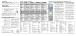
Basic Required Tools

(C) Master Technician or Specialist

(B) Dealer Technician

Instructional Symbols / Definitions

Application Notes

Denotes quality processes to be checked 
prior to moving to the next step

Denotes personal protective equipment (PPEs) that 

may be required for a step.  Examples of safety 

equipment icons noted below:

Denotes specific tools that are necessary 
to complete a step

#2 Phillips 

Screwdriver

Denotes cautions to be taken to avoid 
physical injury or electronic component 
damage

Vehicle must be equipped with mechanical key start.

Ensure vehicle does NOT have SMART KEY (PUSH BUTTON IGNITION SYSTEM).

Vehicle should be equipped with automatic transmission, power door locks, and power windows.  If these features are not equipped on the vehicle, do not proceed with install.

(1) 855-225-7344

M~F - 9am~5pm Pacific Standard Time

The order of  the disassembly and reassembly steps have been optimized for maximum efficiency and the correct 
installation of the Remote Engine Start kit. Disassemble vehicle components (including harness connectors) and 
install the kit components according to each step, as indicated. Avoid disassembling or reassembling any 
components in advance to prevent unnecessary labor time and/or installation errors.

Denotes warnings that may lead to serious 
physical injury or vehicle damage

0.87

0.39

lbs

kg

All dealers must determine if the weight they have added in the form of  all options or accessories, when added to the weight of all Port/Dealer Installed 
options or accessories, exceeds the lesser of 1.5% of GVWR or 100 lbs.  If the additional weight does exceed the lesser of the indicated thresholds, a “Load 
Carrying Capacity Reduced” label must be installed.  A black, fine-point, indelible marker must be used to write by hand onto the label, the reduced carrying 
capacity in kilograms or pounds, which is the total weight of all added options and accessories.     

Load Label Part Number:  NP070-09003

Revision Date

5/03/2018

Page 1 of 11

Summary of Contents for S2F57 AC300

Page 1: ...ian Instructional Symbols Definitions Application Notes Denotes quality processes to be checked prior to moving to the next step Denotes personal protective equipment PPEs that may be required for a step Examples of safety equipment icons noted below Denotes specific tools that are necessary to complete a step 2 Phillips Screwdriver Denotes cautions to be taken to avoid physical injury or electron...

Page 2: ...ors listen for a click indicating they are securely locked 9 FM1 AM2 Special Instructions A FM9 AM3 FM3 1 Antenna Harness FM2 Wire Tie SAT2 SAT3 SAT4 AM1 FM6 FM5 FM7 FM8 1 S P S2F57 AC230 2 1 Way Transmitter Fob Qty FM10 SAT1 S P S2F57 AC340 S P 1WF57 AC340 Kit Overview S P S2F57 ACD10 Qty Description Control Module 1 Harness SAT5 AM5 AM4 FM4 1 S P S2F57 AC120 S P A9F57 AC170 Hardware Total 1 1 An...

Page 3: ... the vehicle s Negative Battery Cover B Disconnect and isolate the vehicle s Negative Battery Cable 2 A Lower the Driver s Door Window B Move the Driver s Seat to the rearmost position C Record all pre set radio stations if applicable D Pull the Hood Lever to open the Hood Ratchet Extension and 10mm Deep Socket Negative Battery Cable Step 12 Ground Steps 10 11 CAN Connectors Multi Box Steps 8 9 Ig...

Page 4: ...ash Panel Fuse Panel Cover or Dash End Cap Make sure no pressure clips remain in the dash board A Dislodge the Weatherstrip from the Driver s Kick Panel along the Door Threshold Panel B Remove the Driver s Door Threshold Panel C Remove the Hood Release Lever D Remove the Driver s Kick Panel E Store the removed parts in a safe location for reinstallation 3 Trim Removal Tool 6 Trim Removal Tool A Us...

Page 5: ... not damage the Steering Column Shroud Steering Wheel Ignition Switch Connector or Steering Column Caution Make sure that both 6 pin connectors are fully locked together 7 NOTE To access screws insert key and turn to the ACC position in order to prevent steering wheel from locking Caution Do not damage the Steering Column Shroud Steering Wheel or Steering Column A Unplug the Factory 6 Pin Female C...

Page 6: ...xcess Wire Tie material N O T E Caution Adjust the Remote Start Ignition Harness and Factory Ignition Harness as needed to make sure there are no rub pinch areas or contact points with steering column components and the tilt mechanism springs as noted above Readjust the ties harnesses if necessary to prevent contact 9 Wire Cutters Wire Ties Factory Ignition Harness Remote Start Harness Remote Star...

Page 7: ... bracket located by the Fuse Box as shown B Route the Ground wire as shown over to Dash Bolt area C Insert the 12mm Dash Bolt into the Ground wire Ring Terminal and reinstall D Torque to 19 2 N m 1 96 kgf m 14 16 lb ft Caution Make sure the Remote Start Harness does not interfere with the re installation of the Driver s Kick Panel 13 Wire Cutters N O T E A Using two 2 Wire Ties secure the Remote S...

Page 8: ...ry Harness as shown C Trim excess Wire Tie material 16 N O T E A Clean the left top surface of the Radiator Cover Ensure the surface is completely dry B Remove the Adhesive Liner from the Warning Label then secure the label to the Radiator Cover as shown up against the raised front edge of the cover A Reconnect the Negative Battery Cable Torque to 5 0 6 0 N m 0 5 0 6 kgf m 45 52 lb in B Reinstall ...

Page 9: ...e with the original Fob or oldest available Fob 18 19 GO TO Function Check A Remote Start Transmitter Fob Pairing Procedure not necessary for new installations only needed if a fob is replaced N O T E A Perform the Function Check at the end of the Instructions N O T E A Reinstall the Lower and Upper Steering Column Shroud removed in Step 7 B Dislodge the Driver s Side Door Weatherstrip from the da...

Page 10: ...o be Checked The engine will stop immediately 1 Press button one time 2 Within 3 seconds press and hold button for 2 seconds 1 Press button 2 times 2 Press button 2 more times 1 Press button one time All doors hood trunk are closed While the vehicle is running via remote start 1 Press button two 2 times 2 Press button two 2 additional times While the vehicle is running via remote start 1 Press but...

Page 11: ...Genuine Accessories Wiring Diagram Revision Date 5 03 2018 Page 11 of 11 ...

Reviews: