44
MAXPRO200
Instruction Manual 807700 Revision 1
Installation
Recommended grounding and shielding practices
Introduction
This section describes practices for grounding and shielding to protect a plasma cutting system against radio frequency
interference (RFI) and electromagnetic interference (EMI) (also called
noise
). It also describes the DC power ground and
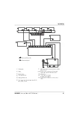
the service ground. The diagram at the end of this section shows these types of grounds in a plasma cutting system.
Note:
The grounding practices in this section have been used on many installations with excellent results, and
Hypertherm recommends that these practices be a routine part of the installation process. The actual methods
used to implement these practices may vary from system to system, but should remain as consistent as possible.
However, due to the variation in equipment and installations, these grounding practices may not succeed in every
case to eliminate RFI/EMI noise issues.
Types of grounding
Service ground
(also called safety ground or potential earth (PE) ground) is the grounding system that applies to the
incoming line voltage. It prevents a shock hazard to any personnel from any of the equipment or the cutting
table. It includes the service ground coming into the plasma system and other systems such as the CNC
and the motor drives, as well as the supplemental ground rod connected to the cutting table. In the plasma
circuits, the ground is carried from the plasma system chassis to the chassis of each separate console
through the interconnecting cables.
DC power ground
(also called cutting current ground) is the grounding system that completes the path of the cutting
current from the torch back to the plasma system. It requires that the positive lead from the plasma system
be firmly connected to the cutting table ground bus with a properly sized cables. It also requires that the
slats, on which the workpiece rests, make firm contact with the table and the workpiece.
RFI and EMI grounding and shielding
is the grounding system that limits the amount of electrical noise emitted by
the plasma and motor drive systems. It also limits the amount of noise that is received by the CNC and
other control and measurement circuits. The grounding practices described in this section mainly target
RFI and EMI grounding and shielding.
Grounding practices
1.
Unless noted, use only 16 mm
2
(6 AWG) welding cable (047040) for the EMI ground cables shown on the diagram.
2.
The cutting table is used for the common, or star, EMI ground point and should have threaded studs welded to the
table with a copper bus bar mounted on them. A separate bus bar should be mounted on the gantry as close to
each motor as possible. If there are motors at each end of the gantry, run a separate EMI ground cable from the
far motor to the gantry bus bar. The gantry bus bar should have a separate, heavy EMI ground cable 21.2 mm
2
(4 AWG; 047031) to the table bus bar. The EMI ground cables for the torch lifter and the RHF console must each
run separately to the table ground bus.
WARNING!
ELECTRIC SHOCK CAN KILL
Disconnect electrical power before performing any maintenance. All work requiring the
removal of the plasma system cover must be performed by a qualified technician.
See the
Safety
section of your instruction manual for more safety precautions.
Summary of Contents for MAXPRO200
Page 1: ...MAXPRO200 Instruction Manual 807700 Revision 1 ...
Page 26: ...22 MAXPRO200 Instruction Manual 807700 Revision 1 Safety ...
Page 34: ...30 MAXPRO200 Instruction Manual 807700 Revision 1 Product Stewardship ...
Page 38: ...34 MAXPRO200 Instruction Manual 807700 Revision 1 Specifications ...


