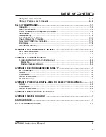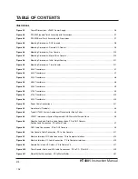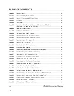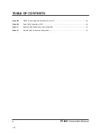
Changed Page
Description
IM200 Rev 3 to 4 12/20/96
0.01
Uprevved due to LVD changes, 360A Beveling consumables, Kip valves
0.03
updated TOC with new safety sections
0.04
changed page of changing consumable parts
1.01-1a.04
new safety section
2.02
removed reference to CE compliance
2.06
removed 380 and 415VAC references
3.11
removed 380-415VAC reference
5.01
changed page numbers for changing consumable parts
5.02 & 5.09
Changed operation of STATUS indicators
5.20
Added 340A beveling, changed 120390 to 120392, added CE warning
5.21-5.24
Added CE retaining caps
5.25
Added CE retaining caps, changed 120390 to 120392
5.26
340A bev ct chrt & consums, CE ret cap, chngd 120390 to 120292
5.27-5.32
Added CE retaining caps
5.33
page bump, added cap removal tool for CE caps
6.05
New Interlock PCB #, new firmware rev (L)
6.07
New chopper #
6.11
New power distribution board #
6.46
New power distribution board #, chopper #, interlock PCB #
7.06
Flow chart change for chopper temp switch and status LED functioning
7.11
removed reference to 380-415V CE power supplies
7.13
New power distribution board graphic
7.15,20 & 21
Changed operation of STATUS indicators
7.23
Removed reference to temp switch on chopper
8.05
Uprevved wiring diagrams to Z (14 pgs)
6.43&45
Removed 120392 ret cap
2.07
Added warning to use CE retaining caps
2.09
New gas console part no.
4.11,23,27 & 29
New picture of gas console rear
4.30
New picture and part no. for off valve cable and hose assy
6.01
Added new CE consumable parts kits to TOC
6.20
New picture of gas console rear
6.21
new part numbers for valves
6.22
New picture of motor valve console
6.23
new part numbers for valves
6.25
New part number for potentiometer
6.38
New picture and part no. for off valve cable and hose assy
6.47
Changed p/n of valve in gas console-recommended spare part
7.14,17 & 18
Changed "light" to "illuminate" - international translation ease
7.28
Added postflow gas control and new picture of control board
5.20-5.45
Changed 120392 to 120390
6.05,7.06 & 20
Changed 24VAC to 12VDC for interlock voltage
6.38
Changed p/n of off-valve cable
6.11 & 46
New power distribution board #
4.10
Added signals for extra valves in cable diagram
4.28
Added signals for extra valves in cable diagram
Page 12
Summary of Contents for HT4001
Page 1: ...Plasma Arc Cutting System Instruction Manual 802000 Revision 15 HT4001 EN50199 EN60974 1 ...
Page 239: ...e 2 ...
Page 240: ...e 3 ...
Page 241: ...e 4 ...
Page 242: ...e 5 ...
Page 244: ...e 7 ...
Page 245: ...e 8 ...
Page 246: ...e 9 ...
Page 247: ...e 10 ...
Page 257: ...KY ...
Page 258: ...KY ...
Page 259: ...KY ...
Page 260: ...KY ...
Page 261: ...KY ...
Page 262: ...KY ...
Page 263: ...KY ...
Page 264: ...KY ...
Page 268: ...KY ...
Page 269: ...KY ...
Page 270: ...KY ...


