background image

DESCRIPTION & SPECIFICATIONS

2-13

HT4001 Instruction Manual

O

I

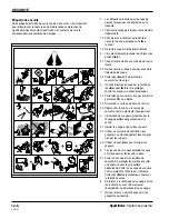
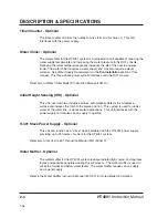
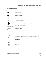
Direct Current (DC).

Alternating current (AC).

Plasma cutting torch.

AC input power connection.

The terminal for the external protective (earthed) conductor.

A  chopper-based power source.

Anode (+) work clamp.

Temperature switch.

Pressure switch.

Plasma torch in the TEST position (cooling and cutting gas exiting nozzle).

The power is on.

The power is off.

Volt/amp curve.

IEC SYMBOLS USED

1-98

Summary of Contents for HT4001

Page 1: ...Plasma Arc Cutting System Instruction Manual 802000 Revision 15 HT4001 EN50199 EN60974 1 ...

Page 2: ...Changed Page Description IM200 Rev 14 to 15 9 18 01 1 1 1a 6 Updated safety sections 0 Updated addresses on subsidiary page Page 1 ...

Page 3: ...lay 4 12 new signals for remote on off 4 13 added graphic TB4 with note about jumper 4 37 new TB4 graphic 6 10 New graphic of power supply rear bail 6 11 part number addition for on off relay 8 05 Uprevved wiring diagrams to KY 14 pages a 4 5 new location of disabling surge injection circuit Page 2 ...

Page 4: ... dimensions for new 401 power supply 7 23 new graphic of chopper a 02 changed slave modification because of HDR 401 power supply a 03 11 changed slave modification because of HDR 401 power supply 8 10 of 14 updated 401 wiring diagram portion of HT4001 schematic Page 3 ...

Page 5: ...47 removed diodes from recommended spare parts 8 05 Uprevved wiring diagrams to KV 14 pages 4 12 added note about DC relay kit 6 21 47 changed ps1 and ps2 to 005243 7 21 changed 100 psi to 80 psi 0 02 added plumbing and electrical codes statement to warranty 3 02 bolded installation by qualified rewrote hard plumbing suggestions 4 14 Added note to check uP board before connecting V C cable 3 05 Ad...

Page 6: ...umbers 7 13 New graphic of power distribution board fuse f4 7 24 27 Updated LEDs on Relay board f 01 04 Added system grounding appendix 8 05 Uprevved wiring diagrams to KU 14 pages 0 05 Added system grounding to TOC 0 10 Added system grounding figures to TOC 4 19 New TB3 figure 4 37 New TB3 figure 6 21 006109 replacing 006066 6 23 006109 replacing 006066 6 47 006109 replacing 006066 Page 5 ...

Page 7: ...are 6 40 Changed graphic part number and description of fig 6 41 a 02 Changed slave kit number and contents a 03 Changed graphic of inside of H 401 power supply i o board eliminated a 04 New directions for installation serial i o board eliminated a 05 Changed labels a 06 bumped page a 08 New graphic p n and signal description a 09 Changed graphic from serial i o pcb to current setpoint pcb c 04 c ...

Page 8: ...hic of in rush protection circuit 6 15 New part no for in rush protection circuit 7 18 bumped text from pg 7 19 7 19 Added troubleshooting for voltage dropping below 15 7 28 Minor text change 7 29 Added error code 15 6 06 Added graphic of phase loss protection circuit 6 07 Added phase loss protection circuit part no 8 05 Uprevved wiring diagrams to KR 14 pages 0 01 Uprevved to 9 3 27 98 with seria...

Page 9: ...igure s 0 07 10 bumped page 2 01 Repaginated due to additional pages 2 05 Added power factor 2 07 Added figures of torches with dimensions 2 08 14 bumped page 4 08 10 20 corrected cable designation in table 6 15 Added chassis SA p n for in rush circuit 6 31 Added 60 lengths to cables i 1 i 6 updated index Page 8 ...

Page 10: ... 04 Added 440V current and fuse specs 3 05 Added 440V cable size recomendation 3 09 Added 440V Transformer picture 4 04 Added torque specification 6 11 Added 440V control xfrmr number 6 13 Added 440V power xfrmr number 8 05 Uprevved wiring diagrams to KM 14 pages 4 26 Added note to see torque specs 4 30 Added note to see torque specs Page 9 ...

Page 11: ...el 3 11 Changed light contactor to lights contactors 4 02 Changed customer service tel 6 14 Changed dwg of power supply rear wall inside 6 15 Added in rush components to parts list 7 09 10 Added CON2 to sequence of operation 7 12 Changed light contactor to lights contactors 8 05 Uprevved wiring diagrams to GG 14 pgs 2 05 changed OCV spec to 361V 7 22 23 Corrected chopper test procedure Page 10 ...

Page 12: ...ts 6 47 Added 011081 float stop 8 05 Uprevved wiring diagrams to EE 14 pgs 0 05 Updated TOC for torch coolant draining 7 01 Added torch coolant draining 7 03 Referenced torch coolant draining 7 30 Added torch coolant draining procedure 4 10 Added omitted signals to gas console cable 0 01 Uprevved to 5 implement 4 14 with serial 514 2 09 Corrected dimension on gas console holes 5 20 Corrected refer...

Page 13: ...rence to 380 415V CE power supplies 7 13 New power distribution board graphic 7 15 20 21 Changed operation of STATUS indicators 7 23 Removed reference to temp switch on chopper 8 05 Uprevved wiring diagrams to Z 14 pgs 6 43 45 Removed 120392 ret cap 2 07 Added warning to use CE retaining caps 2 09 New gas console part no 4 11 23 27 29 New picture of gas console rear 4 30 New picture and part no fo...

Page 14: ...vision 15 September 2001 Copyright 2001 Hypertherm Inc All Rights Reserved Hypertherm HyDefinition HT HyLife LongLife MAX PAC and Powermax are trademarks of Hypertherm Inc and may be registered in the United States and or other countries Hypertherm Inc Hanover NH USA www hypertherm com ...

Page 15: ...ublic of Singapore 65 841 2489 Tel 65 841 2490 Fax 65 841 2489 Technical Service Japan 1952 14 Yata Natsumegi Mishima City Shizuoka Pref 411 0801 Japan 81 0 559 75 7387 Tel 81 0 559 75 7376 Fax Hypertherm UK Ltd 9 Berkeley Court Manor Park Runcorn Cheshire England WA7 1TQ 44 1928 579 074 Tel 44 1928 579 604 Fax France 15 Impasse des Rosiers 95610 Eragny France 0805 050 111 Tel 0805 050 222 Fax Hyp...

Page 16: ...C COMPATIBILITY EMC ATTENTION The 380 415V CE power supply complies with the EMC European standard EN50199 Information about this standard and other line filtering information pertaining to this power supply is located in Appendix C of this manual 1 96 ...

Page 17: ...y Hypertherm or manufactured by a person other than Hypertherm not in strict conformity with Hypertherm s specifications and in cases of designs processes formulae or combinations not developed or purported to be developed by Hypertherm Hypertherm will defend or settle at its own expense any suit or proceeding brought against you alleging that the use of the Hypertherm product alone and not in com...

Page 18: ...vre les instructions de sécurité 1a 2 Le coupage peut provoquer un incendie ou une explosion 1a 2 Les chocs électriques peuvent être fatals 1a 3 Le coupage peut produire des vapeurs toxiques 1a 3 L arc plasma peut provoquer des blessures ou des brûlures 1a 4 Mise à la masse et à la terre 1a 4 Les rayons de l arc peuvent brûler les yeux et la peau 1a 4 Sécurité des bouteilles de gaz comprimé 1a 5 L...

Page 19: ...ction 5 OPERATION 5 1 Controls and Indicators 5 2 Pre Operation System Checkout 5 8 Daily Start Up 5 13 Cutting Techniques 5 15 Common Cutting Faults 5 19 Technical Questions 5 19 Cut Charts 5 19 Cut Chart and Consumable Parts Index 5 20 Changing Consumable Parts 5 33 Section 6 Parts List 6 1 Introduction 6 2 Finding Part Numbers 6 2 HT4001 Interconnection Reference Map 6 3 HT4001 Power Supply 6 5...

Page 20: ...30 APPENDIX A H 401 POWER SUPPLY AS SLAVE a 1 H 401 Slave Modification a 2 H 401 Slave Connections a 6 APPENDIX B AERATION MANIFOLD b 1 Aeration Manifold for Plasma Cutting Aluminum b 2 Introduction b 2 Making an Aeration Manifold b 2 APPENDIX C ELECTROMAGNETIC COMPATIBILITY c 1 EMC Introduction c 2 General c 3 Power Cable c 3 Connect Power Cable c 3 EMI Filter Parts List c 6 APPENDIX D POWER CABL...

Page 21: ...415V Transformer 3 9 Figure 3 7 575V Transformer 3 10 Figure 3 8 600V Transformer 3 10 Figure 3 9 Power Cable Connections 3 11 Figure 4 1 Noise Levels Decibels 4 3 Figure 4 2 Typical HT4001 System Component Placement for Gantry Cutter 4 4 Figure 4 3 HT4001 Interconnect System Diagram with IHS Water Muffler and Slave 4 5 Figure 4 4 Negative Lead and Pilot Arc Lead Connections PS to RHF Console Posi...

Page 22: ... 3 Gas Console Front Panel Controls and Indicators 5 5 Figure 5 4 Digital Remote DR V C Front Panel Controls and Indicators 5 6 Figure 5 5 Programmable Remote PR V C Front Panel Indicators 5 7 Figure 5 6 Timer Counter Front Panel Indicators 5 7 Figure 5 7 Gas Console Reference Pre Operation 5 8 Figure 5 8 Torch with Inductive Probes 5 11 Figure 5 9 Gas Console Reference Daily Startup 5 14 Figure 5...

Page 23: ...ace Cable PS to IHS 6 34 Figure 6 25 Water Muffler Air Control Cable PS to Water Muffler Air Control Box 6 34 Figure 6 26 Water Muffler Pump Cable PS to Water Muffler Pump 6 34 Figure 6 27 Cooling Hose Set RHF Console to Water Chiller 6 35 Figure 6 28 Injection Water Hose RHF Console to Gas Console 6 35 Figure 6 29 Shielded Torch Leads RHF Console to Torch 6 36 Figure 6 30 Oxygen Supply Hose Gas C...

Page 24: ... O2 Test Preflow 7 25 Figure 7 6 Relay Board PCB4 in N2 Test Preflow 7 25 Figure 7 7 Relay Board PCB4 in O2 Test Cut Flow 7 26 Figure 7 8 Relay Board PCB4 in N2 Test Cut Flow 7 26 Figure 7 9 Relay Board PCB4 in RUN Mode 7 27 Figure a 1 Current Setpoint PCB Installation a 3 Figure a 2 Current Setpoint PCB Connections a 5 Figure a 3 H 401 Terminal Strip Connections a 5 Figure a 4 H 401 Power Cable C...

Page 25: ...Manual x Figure d 2 HT4001 Power Supply with Terminal Box Cover Off d 3 Figure d 3 Power Cable Connections to TB5 d 4 Figure f 1 Recommended Ground Connection Configuration f 2 Figure f 2 Alternate Ground Connection Configuration f 3 7 98 ...

Page 26: ...n Kill 1 3 Cutting Can Produce Toxic Fumes 1 3 A Plasma Arc Can Cause Injury and Burns 1 4 Arc Rays Can Burn Eyes and Skin 1 4 Grounding Safety 1 4 Compressed Gas Equipment Safety 1 5 Gas Cylinders Can Explode If Damaged 1 5 Noise Can Damage Hearing 1 5 Pacemaker and Hearing Aid Operation 1 5 A Plasma Arc Can Damage Frozen Pipes 1 5 Additional Safety Information 1 5 Warning Label 1 6 ...

Page 27: ... sure the area is safe before doing any cutting Keep a fire extinguisher nearby Remove all flammables within 35 feet 10 m of the cutting area Quench hot metal or allow it to cool before handling or before letting it touch combustible materials Never cut containers with potentially flammable materials inside they must be emptied and properly cleaned first Ventilate potentially flammable atmospheres...

Page 28: ... on the workbench with the work cable attached during the cutting process Before checking cleaning or changing torch parts disconnect the main power or unplug the power supply Never bypass or shortcut the safety interlocks Before removing any power supply or system enclosure cover disconnect electrical input power Wait 5 minutes after disconnecting the main power to allow capacitors to discharge N...

Page 29: ...ant clothing to cover all exposed areas Cuffless trousers to prevent entry of sparks and slag Remove any combustibles such as a butane lighter or matches from your pockets before cutting Cutting Area Prepare the cutting area to reduce reflection and transmission of ultraviolet light Paint walls and other surfaces with dark colors to reduce reflection Use protective screens or barriers to protect o...

Page 30: ...s possible to the work cable Do not wrap or drape the torch lead or work cable around your body Keep as far away from the power supply as possible PACEMAKER AND HEARING AID OPERATION ADDITIONAL SAFETY INFORMATION 1 ANSI Standard Z49 1 Safety in Welding and Cutting American Welding Society 550 LeJeune Road P O Box 351020 Miami FL 33135 2 ANSI Standard Z49 2 Fire Prevention in the Use of Cutting and...

Page 31: ...ing path 2 3 Wear complete body protection 3 Electric shock from torch or wiring can kill Protect yourself from electric shock 3 1 Wear insulating gloves Do not wear wet or damaged gloves 3 2 Insulate yourself from work and ground 3 3 Disconnect input plug or power before working on machine 4 Breathing cutting fumes can be hazardous to your health 4 1 Keep your head out of the fumes 4 2 Use forced...

Page 32: ...vention des chocs électriques 1a 3 Le coupage peut produire des vapeurs toxiques 1a 3 L arc plasma peut provoquer des blessures ou des brûlures 1a 4 Torches à allumage instantané 1a 4 Les rayons de l arc peuvent brûler les yeux et la peau 1a 4 Protection des yeux Protection de la peau Zone de coupage 1a 4 Mise à la masse et à la terre 1a 4 Câble de retour Table de travail Alimentation 1a 4 Sécurit...

Page 33: ...e sont pas suivies correctement Prévention des incendies Avant de commencer s assurer que la zone de coupage ne présente aucun danger Conserver un extincteur à proximité Éloigner toute matière inflammable à une distance d au moins 10 m du poste de coupage Tremper le métal chaud ou le laisser refroidir avant de le manipuler ou avant de le mettre en contact avec des matériaux combustibles Ne jamais ...

Page 34: ...lors du coupage Laisser la pièce à couper en place ou sur la table de travail le câble de retour connecté lors du coupage Avant de vérifier de nettoyer ou de remplacer les pièces de la torche couper l alimentation ou débrancher la prise de courant Ne jamais contourner ou court circuiter les verrouillages de sécurité Avant d enlever le capot du système ou de la source de courant couper l alimentati...

Page 35: ...osées du corps Pantalon sans revers pour éviter que des étincelles ou des scories puissent s y loger Avant le coupage retirer de ses poches tout objet combustible comme les briquets au butane ou les allumettes Zone de coupage Préparer la zone de coupage afin de réduire la réverbération et la transmission de la lumière ultraviolette Peindre les murs et autres surfaces de couleur sombre pour réduire...

Page 36: ...e jamais exposer des bouteilles à une chaleur excessive aux étincelles aux scories ou aux flammes nues Ne jamais utiliser des marteaux des clés ou d autres outils pour débloquer le robinet des bouteilles Une exposition prolongée au bruit du coupage ou du gougeage peut provoquer des problèmes auditifs Utiliser un casque de protection homologué lors de l utilisation du système plasma Prévenir les pe...

Page 37: ...t être fatal Se protéger contre les risques de chocs électriques 3 1 Porter des gants isolants Ne pas porter de gants mouillés ou abîmés 3 2 S isoler de la surface de travail et du sol 3 3 Débrancher la prise ou la source de courant avant de manipuler l équipement 4 L inhalation des vapeurs produites par le coupage peut être dangereuse pour la santé 4 1 Garder le visage à l écart des vapeurs 4 2 U...

Page 38: ...01 Slave Power Supply Optional 2 4 Water Muffler Optional 2 4 Specifications 2 5 System Requirements 2 5 HT4001 Power Supply 2 5 HT4001 Power Supply with Slave 2 5 PAC620 Machine Torches 2 7 Remote High Frequency Console 2 8 Digital Remote DR V C Control 2 9 Programmable Remote PR V C Control 2 9 Gas Console 2 10 Motor Valve Console 2 10 Initial Height Sensing 2 11 Timer Counter 2 11 Water Chiller...

Page 39: ...nge of cut thicknesses The plasma gases used with the HT4001 system are oxygen for cutting mild steel and nitrogen for cutting stainless steel aluminum and other non ferrous materials The following descriptions briefly describe the purpose and configuration of the HT4001 System components HT4001 Power Supply This unit houses four 100 amp 15 kHz chopper power supplies to produce constant current DC...

Page 40: ...de accurate operator control of the arc voltage and current High intensity LED displays indicate the setpoints for volts and amperes prior to starting the arc After the arc is initiated the displays automatically indicate the actual values of the voltage and current reached The current remote does not come with LED displays a thumbwheel switch is provided to set current only These units interface ...

Page 41: ...l 802410 Initial Height Sensing IHS Optional This unit used with two inductive probes automatically detects the workpiece surface and indexes the torch to the pierce position This system is used for under water at the water line or above water applications This unit interfaces with the power supply and requires an air supply to operate H 401 Slave Power Supply Optional This unit can function as a ...

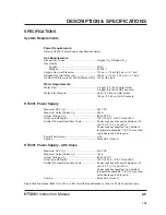
Page 42: ...61 VDC Maximum Output Current I2 400 A Output Voltage U2 80 200 VDC Duty Cycle Rating X 100 40 C at 400 A and 200 V Ambient Temperatures Duty Cycle Power supplies will operate between 14 and 104 F 10 and 40 C Power supplies operated in an ambient temperature above 86 F 30 C may show some decrease in duty cycle Power Factor cosϕ 0 94 Cooling Forced Air Class F HT4001 Power Supply with Slave Maximum...

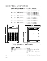
Page 43: ...77023 without THC 400 VAC U1 CE 3Ø 50 60 Hz 128A I1 077031 with THC 077030 without THC 440 VAC U1 3Ø 50 Hz 117A I1 480 VAC U1 3Ø 50 Hz 107A I1 077004 with THC 077018 without THC 240 VAC U1 3Ø 60 Hz 214A I1 480 VAC U1 3Ø 60 Hz 107A I1 077005 with THC 077019 without THC 575 VAC U1 3Ø 60 Hz 89A I1 600 VAC U1 3Ø 60 Hz 86A I1 Figure 2 1 Overall Dimensions HT4001 Power Supply 11 97 Dimensions and Weight...

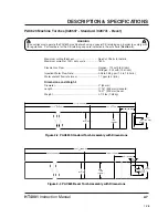
Page 44: ... 2 50 mm Length 17 15 435 mm standard 15 37 390 mm bevel Weight 3 1 2 lbs 1 58 kg WARNING CE countries must operate the PAC620 machine torch using a special CE retaining cap in order to comply with CE regulations Part numbers for the CE retaining caps are indicated in the cut charts Section 5 1 98 Figure 2 2 PAC620 Standard Torch Assembly with Dimensions Figure 2 3 PAC620 Bevel Torch Assembly with...

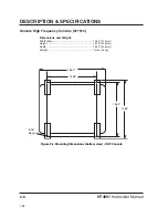
Page 45: ...tion Manual Remote High Frequency Console 077010 Dimensions and Weight Width Max 14 63 372 mm Height 16 75 425 mm Depth 16 00 406 mm Weight 75 lbs 34 kg 16 00 12 38 13 63 14 63 5 16 dia 4 Figure 2 4 Mounting Dimensions bottom view RHF Console 1 98 ...

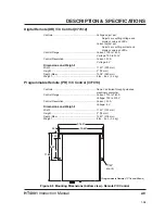
Page 46: ...tting current and displays value on LEDs Control Range Current 100 to 760 A Voltage 100 to 200 V Control Resolution Current 20 A Voltage 5 V Dimensions and Weight Width 11 40 290 mm Height 3 76 mm Depth Max 13 38 340 mm Weight 5 lbs 5 oz 2 4 kg Programmable Remote PR V C Control 077013 Controls None Controlled through guidance machinery computer Control Range Current 100 to 760 A Voltage 100 to 20...

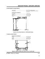
Page 47: ...gure 2 6 Mounting Dimensions bottom view Gas Console Motor Valve Console 073214 Dimensions and Weight Width 11 50 290 mm Height 4 25 110 mm Depth 8 200 mm Weight 14 lbs 6 3 kg Figure 2 7 Mounting Dimensions bottom view Motor Valve Console 11 50 10 75 10 25 8 7 6 5 16 dia 4 4 1 2 2 3 3 4 3 3 4 2 1 4 20 PEM Use 1 4 20 screws that do not enter more than 1 2 into enclosure 1 98 3 ...

Page 48: ...pth 8 50 220 mm Weight 3 lbs 1 kg 8 50 6 50 3 38 1 70 6 25 50 5 32 dia 4 Figure 2 9 Mounting Dimensions bottom view Timer Counter 10 75 11 50 5 16 dia 4 8 6 1 98 Initial Height Sensing 053016 Input Power 120 VAC from power supply Air Pressure 20 psi 1 4 bar regulated shop air input to solenoid Dimensions and Weight Width Max 9 230 mm Height 4 50 110 mm Depth Max 11 5 290 mm Weight 13 lbs 6 kg ...

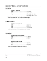
Page 49: ...struction Manual 802410 H 401 Power Supply H 401 Dimensions and Weight Width 40 1025 mm Height 53 1345 mm Depth 50 1270 mm Weight 2250 lbs 1022 kg Refer also to H 401 H 601 Instruction Manual IM41 800410 Water Muffler Air Control Dimensions and Weight Width 6 25 160 mm Height 6 25 160 mm Depth 4 25 110 mm Weight 6 lbs 2 7 kg Pump Dimensions and Weight Width 11 280 mm Height 19 480 mm Depth 17 430 ...

Page 50: ...ng torch AC input power connection The terminal for the external protective earthed conductor A chopper based power source Anode work clamp Temperature switch Pressure switch Plasma torch in the TEST position cooling and cutting gas exiting nozzle The power is on The power is off Volt amp curve IEC SYMBOLS USED 1 98 ...

Page 51: ...ding Requirements 3 4 Power Requirements 3 4 Line Disconnect Switch 3 5 Power Cables 3 5 Positioning the Power Supplies 3 6 Transformer Configurations 3 7 Connecting the Power 3 11 Torch Lifter Requirement 3 12 Optional Equipment 3 12 Water Muffler 3 12 Initial Height Sensing IHS 3 13 HT4001 Instruction Manual 3 1 15 ...

Page 52: ...ecrease and parts life can shorten If making hard plumbing connections avoid using iron pipe Never use teflon tape on any joint preparation After installation pressurize the entire system and check for leaks From Source Supply to Gas Console The customer must provide a regulator capable of delivering the following Oxygen 120 psi 10 psi 8 3 bar 0 7 bar to the gas console Nitrogen 150 psi 10 psi 10 ...

Page 53: ...s filtering the inlet line Purchase filters locally or from Hypertherm Refer to water chiller instruction manual 802410 Model D for additional information on the water chiller Refer also to Routine Maintenance in Section 7 for instructions on how to protect copper surfaces in the water chiller loop Water Quality A low level of calcium carbonate measured in water hardness is critical for proper per...

Page 54: ...ing Electrode System or other appropriate code POWER REQUIREMENTS WARNING Electrical installation must be performed by qualified personnel only All switches slow blow fuses and power cables are customer supplied and must be chosen as directed by applicable national and or local electrical codes Use a separate primary line disconnect switch for each HT4001 power supply and slave Note Input voltage ...

Page 55: ... 0 AWG 125 amps 480 VAC 1 AWG 110 amps 575 VAC 2 AWG 95 amps 600 VAC 2 AWG 95 amps Water Chiller For information on cable sizes for the water chiller refer to its instruction manual 802410 Model D H 401 Slave For information on cable sizes for the H 401 slave refer to its instruction manual 800410 12 99 t u p n I e g a t l o V e g a t l o V e g a t l o V e g a t l o V e g a t l o V G W A r o M C M...

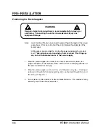
Page 56: ...he power supplies with a crane or hoist Take extra care when moving by hoist or crane The lifting eye may not be the balanced center of the power supply 1 Place the power supplies in an area that is free of excessive moisture has proper ventilation and is relatively clean Allow room for accessing the sides of the power supplies for servicing 2 Place the power supplies so that air flow is not block...

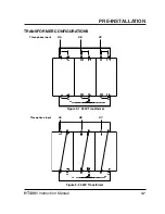
Page 57: ...PRE INSTALLATION 3 7 HT4001 Instruction Manual TRANSFORMER CONFIGURATIONS ØA ØB ØC Three phase input ØA ØB ØC Figure 3 1 240V Transformer Figure 3 2 480V Transformer Three phase input ...

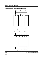
Page 58: ...HT4001 Instruction Manual 3 8 PRE INSTALLATION TRANSFORMER CONFIGURATIONS cont Figure 3 4 380V Transformer ØA ØB ØC Figure 3 3 200V Transformer ØA ØB ØC 10 95 ...

Page 59: ...PRE INSTALLATION 3 9 HT4001 Instruction Manual TRANSFORMER CONFIGURATIONS cont Figure 3 6 415V Transformer Figure 3 5 400V Transformer ØA ØB ØC ØB ØC ØA ØA ØB ØC Figure 3 6a 440V Transformer 11 97 ...

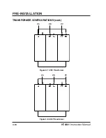
Page 60: ...HT4001 Instruction Manual 3 10 PRE INSTALLATION TRANSFORMER CONFIGURATIONS cont Figure 3 8 600V Transformer Figure 3 7 575V Transformer ØC ØB ØA ØC ØB ØA ...

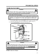
Page 61: ...er power supplies use the procedure below 1 Insert the Power Cable through the Strain Relief located in the rear of the power supply 2 Connect the power leads to the L1 L2 and L3 terminals of CON1 See Fig 3 9 3 Connect the Ground PE lead to the stud as shown in Fig 3 9 8 97 WARNING The neon lights attached to the contactors will turn ON as soon as the line disconnect switch is ON These indicators ...

Page 62: ... min with positive braking A unit which drifts through the stop point is not acceptable OPTIONAL EQUIPMENT Water Muffler The water table provides the supply of water for the water muffler pump This water must be filtered for the water muffler system Hypertherm provides a filter 027009 with all water muffler systems Important Place the pump as close as possible to the water table Longer distances r...

Page 63: ... 3Ø 50 Hz 034131 wo hoses 028308 575 Volt 3Ø 60 Hz Air Requirements Provide a clean dry oil free source of air with a delivery pressure between 80 and 120 psi 5 5 and 8 3 bar with a minimum flow rate of 20 scfm For further information please refer to Hypertherm water muffler instruction manual 801730 Initial Height Sensing IHS The customer must provide a source of compressed air to the Initial Hei...

Page 64: ...ts Placement 4 4 HT4001 Interconnection Reference Map 4 5 Power Supply Connections 4 6 RHF Console Connections 4 22 Gas Console Connections 4 26 Motor Valve Console Connections 4 30 Initial Height Sensing Connections 4 32 Optional Power Supply Connections 4 36 Mounting the Machine Torch 4 38 Torch Alignment 4 38 4 1 HT4001 Instruction Manual 15 ...

Page 65: ...erchandise below for details HT4001 System Components HT4001 Power Supply Remote High Frequency Console Remote Voltage Current Control Gas Console Motor Valve Console Cables Hoses Optional Units Torch lead set to Motor Valve Console Initial Height Sensing Shielded torch lead set to RHF Console Water Muffler System Machine torch Timer Counter Consumable spare parts kit H 401 Slave Water Chiller CLA...

Page 66: ...ect box Ensure the power cord ground wire is properly connected to the HT4001 power supply chassis Refer to Connecting the Power in the Pre Installation section of this manual Ensure that all electrical connections are tight to avoid excessive heating NOISE LEVELS DECIBELS Figure 4 1 presents the noise levels in decibels experienced by an operator standing 10 feet 3 m from the torch in a confined ...

Page 67: ...s Gas or water Torque Specification hose size lbf in lbf ft kgf cm Up to 3 8 9 5 mm 75 85 6 25 7 86 98 1 2 12 7 mm 360 480 30 40 415 550 H 401 Slave optional HT4001 Timer Counter Machine Interface Motor Valve Console Water Chiller Gas Console mount near operator Remote V C Control mount near operator RHF Console Water Muffler Pump IHS Probe Torch Power Air Air Water Muffler Power Power IHS Console...

Page 68: ...34 1234 1234 1234 1234 1234 1234 1234 1234 1234 1234 Work table H2 O in W M Supply 3 Phase Power 3 Phase Power Motor Valve Console Off Valve Timer Counter Gas Console N2 in O2 in 18 Machine Computer Interface W M Air Control Air in 3 Phase Power 1 H 401 or H 601 Slave 11 15 4 5 19 8 13 14 3 10 22 23 20 17 To Second HT4001 System 29 27 Figure 4 3 HT4001 Interconnect System Diagram with IHS Water Mu...

Page 69: ...gh Frequency RHF Console Pass the negative 2 lead through one of the 2 bushings in the lower rear of the HT4001 power supply and connect to the lower bar on the center bail rear as shown in Fig 4 4 Connect the other end of the negative lead securely to the cathode block in the RHF console See part number information below under Positive Lead PS to Work Table 3 Positive Lead PS to Work Table Pass t...

Page 70: ...Negative Lead and Nozzle Lead Connections PS to RHF Console Positive Lead Connection PS to Work Table RHF Console 5 00 RHF Console Power Supply 2 3 3 Work Table Center Bail Rear Start Circuit Assembly on Center Bail Front 4 Inductor Coil 2 Cathode Block 4 ...

Page 71: ... H2 O 8 WHITE 5 Gnd 9 SHIELD CUT FS2 Flow SW 10 BLACK 10 FS2 Flow SW 11 GREEN 13 Gnd 12 SHIELD CUT FS1 Flow SW 23 BLACK 7 PS1 Pressure SW 24 BLUE 8 Gnd 25 SHIELD CUT S1 S2 Door Intlk 34 BLACK 1 S1 S2 Door Intlk 35 YELLOW 4 Gnd 36 SHIELD CUT CR1 28 BROWN 9 Pilot Arc Relay 21 BLACK 11 Gnd 26 SHIELD CUT CR2 5 ORANGE 3 6 BLACK 6 Gnd 7 SHIELD CUT Part No Length Part No Length 023764 50 ft 15 m 023767 1...

Page 72: ...INSTALLATION 4 9 HT4001 Instruction Manual Figure 4 5 RHF Cable Connections PS to RHF Console 2X1 5 RHF Console Power Supply WATER OUT IN NEGATIVE NOZZLE 5 6 96 ...

Page 73: ...WHITE 6 Gnd 1 SHIELD 1 S2 Test Preflow 2 BLACK 2 S2 Test Preflow 3 GREEN 3 Gnd 7 SHIELD 7 S2 Test Cut Flow 8 BLACK 8 S2 Test Cut Flow 9 BLUE 9 Gnd 4 SHIELD 4 SV4A Preflow Cut 16 BLACK 16 SV4A Preflow Cut 17 YELLOW 17 Gnd 10 SHIELD 10 SV4B Preflow Cut 23 RED 23 SV4B Preflow Cut 24 YELLOW 24 Gnd 25 SHIELD 25 SV2 SV3 O2 N2 Preflow 11 BLACK 11 SV2 SV3 O2 N2 Preflow 12 BROWN 12 Gnd 18 SHIELD 18 SV1A Pl...

Page 74: ...INSTALLATION 4 11 HT4001 Instruction Manual Figure 4 6 Gas Console Cable Connection PS to Gas Console Gas Console 6 Power Supply 3X1 6 12 96 ...

Page 75: ...pen when fully retracted 21 Wht 76 Upper Limit Switch Neutral 20 Shield Cut Upper Limit Switch Shield 28 Yel 80 Plasma Emergency Stop 24VAC Signal Closed stop 33 Red 81 Plasma Emergency Stop Signal 27 Shield Cut Plasma Emergency Stop Shld 34 Red 169 Down Relay Load Solid state rated to switch 24 to 120VAC 1amp DC relay optional Closed Down 29 Blk 170 Down Relay Line 23 Shield Cut Down Relay Shield...

Page 76: ...anual Figure 4 7 Machine Interface I O Cable Connection PS to Computer Interface Machine Computer Interface 7 Power Supply 7 24 VAC AUXILIARY INTER LOCKED WITH AUTO STOP Move jumper to TB4 terminals 2 3 to enable a remote ON OFF switch 5 00 ...

Page 77: ... 023855 75 ft 23 m 023852 25 ft 7 5 m 023856 100 ft 30 5 m 023853 35 ft 10 6 m 023903 125 ft 38 m 023854 50 ft 15 m 023857 150 ft 46 m 023858 200 ft 61 m PS END DESCRIPTION SCKT COLOR 1 Black Current 5 2 Wht Current 10 3 Red Current 20 4 Green Current 40 5 Orange Current 80 6 Blue Current 100 7 White Black Current 200 8 Red Black Current 400 9 Green Black Current 800 10 Shield Shield 11 Blue Black...

Page 78: ...INSTALLATION 4 15 HT4001 Instruction Manual Figure 4 8 Machine Interface V C Cable Connection PS to Computer Interface Machine Computer Interface 8 Power Supply 8 ...

Page 79: ...Black 10 Voltage 40 11 Orange Black 11 Voltage 80 12 Red Black 12 Voltage 100 13 Green White 13 Voltage 200 14 Red White 14 Spare 15 White Black 15 Shield 16 Shld 16 9 Remote Serial Cable PS to Remote V C Connect this cable from the power supply to either the digital or programmable remote See IM191 RCC Installation for installation of Remote Current Control to HT4001 V C End PS End 1X4 Part No Le...

Page 80: ...INSTALLATION 4 17 HT4001 Instruction Manual Figure 4 9 Remote Serial and V C Cables PS to Remote V C Power Supply 9 9 Programmable Remote Digital Remote 9 10 10 5X1 5X1 5X2 ...

Page 81: ... Black 3 Upper Limit Switch Common 9 Shield 5 Drain 11 Blk 9 AC Power 14 White 8 AC Power 7 Shield AC Drain 7 Key 11 Timer Counter Cable PS to Timer Counter Pass the timer counter cable through one of the 2 bushings in the lower rear of the HT4001 power supply and connect to TB3 TB3 is located on the inside rear wall of the power supply Part No Length Part No Length 023789 10 ft 3 m 023792 75 ft 2...

Page 82: ...INSTALLATION 4 19 HT4001 Instruction Manual 12 12 TB3 Power Supply 11 Timer Counter Figure 4 10 Timer Counter Cable and IHS Cable Connections PS to T C PS to IHS 11 X 1 Power Supply IHS Module 11 10 98 ...

Page 83: ...water muffler and detailed information on the water muffler system PS End Air Control Box End PS End Water Muffler Pump End Part No Length 023866 50 ft 15 m 023867 75 ft 23 m 023868 100 ft 31 m PS SIGNAL END 1X10 COLOR 2 Black Water Muffler Coil 4 White AC Neutral 3 Green Ground Part No Length Part No Length 023905 25 ft 7 5 m 023908 100 ft 30 5 m 023906 50 ft 15 m 023909 150 ft 46 m 023907 75 ft ...

Page 84: ...INSTALLATION 4 21 HT4001 Instruction Manual Figure 4 11 Water Muffler Connections PS to Water Muffler Power Supply 13 14 ...

Page 85: ...N of the RHF console to DISCHARGE of the water chiller See instruction manual IM241 802410 for more information on the water chiller Part No Length 028652 10 ft 3 m 028440 15 ft 4 5 m 028653 20 ft 6 m 028441 25 ft 7 5 m 028442 50 ft 15 m Part No Length 028443 75 ft 23 m 028444 100 ft 30 5 m 028445 150 ft 46 m 028637 200 ft 61 m Part No Length 024335 26 in 6 m 024315 5 ft 1 5 m 024046 6 ft 1 8 m 02...

Page 86: ...truction Manual Figure 4 12 RHF Connections to Water Chiller and Gas Console RHF Console Water Chiller RHF Console Gas Console 15 RETURN 15 DISCHARGE OUT IN NEGATIVE NOZZLE WATER 2X1 15 WATER IN 15 WATER OUT TORCH H2 O 16 16 12 96 ...

Page 87: ...e Torch Leads to the Torch 1 Slide the insulating sleeve over the torch leads with the threaded end pointing towards the unconnected torch The insulating sleeve will screw onto the torch later 2 Using a 9 16 open end wrench on the two largest torch fittings and a 1 2 open end wrench on the two largest lead fittings connect the leads to the torch Note color code on torch and torch leads 3 Attach an...

Page 88: ...13 RHF Connections to Torch Shielded Leads 17 Red to Red Green to Green White to White INSULATING SLEEVE THREADED END 17 Red Green RHF Console RHF Console Torch Cathode Block Brass Ring 7 96 Pilot Arc Lead Connection Pilot Arc Lead Pass through opening 17 ...

Page 89: ... open end wrench on the left handed torch fitting and a 7 16 open end wrench on the left handed injection water hose fitting turn the water hose fitting in a counterclockwise direction to tighten 3 Make injection water hose connection at gas console Fig 4 14 See page 4 30 to connect plasma gas lead to torch Left hand fitting Part No Length 024335 26 in 6 m 024315 5 ft 1 5 m 024046 6 ft 1 8 m 02403...

Page 90: ...struction Manual Nitrogen Oxygen 18 19 INSULATING SLEEVE 20 Left hand fitting to left hand fitting Torch Figure 4 14 Gas Console Connections Gas Console to Gas Supplies Gas Console to Torch Gas Console Gas Supplies 12 96 18 19 20 ...

Page 91: ...207 45 ft 13 5 m 024340 50 ft 15 m 024419 56 ft 17 m 024127 60 ft 18 m 024343 75 ft 23 m 23 Gas Console Motor Valve Console Cable Gas Console to Motor Valve Console See page 4 30 for remaining motor valve console connections SIGNAL GC END COLOR MVC END SV4A Preflow Cutflow 16 Black 16 SV4A Preflow Cutflow 17 Yellow 17 Ground 10 Shield 10 SV4B Preflow Cutflow 23 Red 23 SV4B Preflow Cutflow 24 Yello...

Page 92: ...INSTALLATION 4 29 HT4001 Instruction Manual Figure 4 15 Gas Console Connections Gas Console to Motor Valve Console Gas Console Motor Valve Console 4 X 1 Preflow Cutflow 22 21 23 22 3X2 21 23 12 96 ...

Page 93: ...f valve 5 Make plasma off cable and plasma lead connections at the motor valve console Fig 4 16 6 Attach the torch to the torch mounting bracket See Mounting the Machine Torch on page 4 38 Function Motor Valve Wire Color Off Valve 4X2 Conn Plasma Off Vent 1 Black 1 2 Red 2 Drain 3 N A Cut Ground 4 Clear Part No Length 129158 14 ft 4 m MOTOR VALVE CONSOLE CONNECTIONS See page 4 28 for motor valve c...

Page 94: ...LLATION 4 31 HT4001 Instruction Manual Figure 4 16 Motor Valve Console to Torch Connections Plasma Flow 4 X 2 24 24 INSULATING SLEEVE 24 TORCH BODY Motor Valve Console Plasma off valve lead connections 12 95 ...

Page 95: ...page 6 47 Function IHS End Color Probe End Power 15 VDC 4 Red A Common 2 Black B Signal 1 Clear C Shield 3 Braid Part No Length 024144 40 ft 12 m A B C Function Pin Color Power 15 VDC A Brown Common B Blue Signal C Black Part No 005074 28 IHS Sensor Cables IHS Module to IHS Probes The 40 foot sensor cables are components of the IHS leads packages see page 6 47 1 2 3 B A C 2 3 B A C 1 4 4 Part No L...

Page 96: ...4001 Instruction Manual TORCH TYPICAL IHS CONTROL MODULE SWIVEL FITTING 20 PSI REGULATED SHOP AIR 25 26 27 TORCH LIFTER 28 INDUCTIVE PROBES Figure 4 17 Initial Height Sensing Connections AIR CYLINDER TORCH MOUNTING BRACKET ...

Page 97: ...d Use Belden 8761 2 At the upper limit switch connect the common wire black and signal wire clear to the upper limit switch Cut the shield drain wire uninsulated Wrap the cut end with electrician s tape 3 At the IHS control module loosen the two 2 latches and open the front cover 4 Route the cable through the strain relief to connect the cable wires to 1TB 5 Connect the shield drain wire uninsulat...

Page 98: ...INSTALLATION 4 35 HT4001 Instruction Manual IHS CONTROL MODULE UPPER LIMIT SWITCH AND CABLE 1TB 67 4 S TORCH LIFTER Figure 4 18 Initial Height Sensing Upper Limit Switch Connections ...

Page 99: ...Supply Negative Lead PS to H 401 or H 601 Power Supply Positive Lead PS to Work Table Additional lead needed when using slave Negative Lead PS to RHF Console Additional lead needed when using slave When using more than 400 amps of cutting current a slave power supply must be used with the HT4001 power supply See Appendix A for details 34 33 32 31 PS1 PS2 FUNCTION END COLOR END 86 Black 86 Hold sig...

Page 100: ...INSTALLATION 4 37 HT4001 Instruction Manual 24 VAC AUXILIARY INTER LOCKED WITH AUTO STOP Figure 4 19 Hold Cable Connections to TB3 29 5 00 ...

Page 101: ...eeve and not touching the stainless steel torch body Position the torch approximately 25 6 mm from the workpiece 3 Tighten the securing screw s See Pre Operation in Section 5 for final adjustment of torch Torch leads typical Torch sleeve Torch mounting bracket Securing screw Workpiece 25 6mm 0 90 Torch sleeve Torch mounting bracket Securing screws Figure 4 20 Mounting the Machine Torch with IHS pr...

Page 102: ...on System Checkout 5 8 Final Torch Adjustment 5 11 Daily Start Up 5 13 Cutting Techniques 5 15 How to Get Better Cut Quality 5 15 Dross Conditions 5 16 Shape of Cut Surface 5 16 How to Get Longer Consumable Life 5 17 How to Get Better Pierces 5 18 How to Increase Cutting Speed 5 18 Common Cutting Faults 5 19 Technical Questions 5 19 Cut Charts 5 19 Cut Chart and Consumable Parts Index 5 20 Changin...

Page 103: ... is open TRANSFORMER LED When illuminated indicates that either the power supply main transformer or one of the choppers is operating in an unacceptable temperature range COOLING WATER LED When illuminated indicates that the coolant flow to the electrode is inadequate PLASMA GAS LED When illuminated indicates that the plasma gas pressure is inadequate HT4001 Power Supply Rear Panel Control Fig 5 2...

Page 104: ...OPERATION 5 3 HT4001 Instruction Manual Figure 5 1 Power Supply Front Panel Indicators Figure 5 2 Power Supply Rear Panel Circuit Breaker RHF DOOR TRANSFORMER COOLING WATER PLASMA GAS STATUS ...

Page 105: ...ow Used when setting the plasma gas cut flow rate on the N2 or O2 flow meter for cutting conditions as specified in the Cut Charts In this position the contactor is disabled N2 FM1 or O2 FM2 flow meter In test cut flow indicates the percentage of plasma gas flow oxygen or nitrogen required for cutting conditions PLASMA Cut Flow motor valve MV1 Activated by momentary switch Adjusts plasma gas test ...

Page 106: ...OPERATION 5 5 HT4001 Instruction Manual Figure 5 3 Gas Console Front Panel Controls and Indicators HYPERTHERM S1 PG2 PG1 PG3 HT4001 S2 MV3 MV2 MV1 MV4 FM1 FM2 FM3 6 95 ...

Page 107: ...ting arc voltage from 90 to 205 volts Values are chosen from the Cut Charts and depend on the type of metal to cut and metal thickness VOLTAGE LEDs Displays cutting voltage CURRENT Adjust Pot Adjusts the cutting arc current from 90 to 800 amps Values are chosen from the Cut Charts and depend on the type of metal to cut and metal thickness CURRENT LEDs Displays cutting current UP DOWN LEDs Indicate...

Page 108: ... 6 Timer Counter Front Panel Indicators Reset Reset Timer Counter Fig 5 6 Each LCD counter is self powered by a three volt lithium battery STARTS LCD Counter w Reset Indicates the number of arc starts ARC TIME LCD Counter Indicates the cumulative time that the arc is on in hours ERRORS LCD Counter w Reset Indicates the number of times that the arc cut cycle ends before the programmed current ramp ...

Page 109: ... supply and water chiller OFF before proceeding The following procedure is for an HT4001 system with a water chiller an IHS system with upper limit switch and a Digital Remote DR V C control module 1 Set the main disconnect switches for the power supply and the water chiller to OFF 2 Set the S2 toggle switch on the gas console to Run Figure 5 7 Gas Console Reference Pre Operation N2 Press Gauge O2...

Page 110: ...s console to plasma gas N2 or O2 8 Set the main disconnect switch for the power supply to ON and throw the POWER circuit breaker on the rear of the power supply to the UP position Verify that the POWER AC indicator illuminates 9 Set the VOLTAGE and CURRENT on the DR V C module Select the arc current and voltage from the Cut Charts for the type and thickness of metal to test cut Notes If using the ...

Page 111: ...etal on the work table to make a test pierce With manual starting there is no machine motion Note The cutting machine must retract the torch at least one inch 25 4 mm from the work before the start cycle or probes may hit the workpiece when START button is depressed 17 Set initial height to ON 18 Depress the START button on your system The probes will immediately descend and the torch will index t...

Page 112: ...ill cut at the torch standoff distance after making the pierce Tighten the securing screw at this position Note If not using the IHS adjust the initial torch height in the standard mounting bracket to twice the torch standoff distance Note also If arc does not transfer when set at twice the torch standoff in the case of thick metal being cut at high current gradually lower the initial height of th...

Page 113: ...stand off distance from the workpiece remains constant and the DOWN indicator lights on the DR V C module As the torch travels from a low point to a high point verify that the torch stand off distance from the workpiece remains constant and the UP indicator lights on the DR V C module As the torch makes a corner cut the machine motion speed should remain constant The UP and DOWN indicators will no...

Page 114: ...N 5 Turn the supply gases ON Set the pressure on the nitrogen supply to read 150 psi 10 psi 10 3 bar 0 7 bar at the N2 pressure gauge on the gas console Set the pressure on the oxygen supply to read 120 psi 10 psi 8 3 bar 0 7 bar at the O2 pressure gauge on the gas console 6 Turn the water supply to the water chiller ON 7 Turn on the water chiller by depressing the START switch 8 Set S1 on the gas...

Page 115: ... to Test Cut Flow Set the cut flow rate on the O2 or N2 flow meters using the MV1 metering valve momentary switch Select the test cut flow rates from the Cut Charts Note If the power supply has been off for more than one hour or if you have changed consumable parts or have changed gases purge gas lines by leaving system in TEST PREFLOW for one minute 13 Check the water flow rate at the water flow ...

Page 116: ...high A negative cut angle indicates a standoff that is too low Vary the arc voltage to correct the cut angle Damaged consumable parts If the nozzle orifice is worn uniformly the cut angle will show positive Check and replace consumables if necessary Refer to Changing Consumable Parts later in this section Machine travel is in the wrong direction The square cut angle is on the right with respect to...

Page 117: ...travel speed If this does not remove the dross lower the torch standoff distance by decreasing arc voltage 3 Dross comes and goes Caused by worn consumable parts Dross can be material dependent Dross formation dependent on metal temperature Warm and hot metal is much more prone to dross accumulation than cool metal For example the first cut in a series of cuts will most likely have the least amoun...

Page 118: ...r to properly ramp down the gases to extend consumable life the torch must end its cut while over metal The plasma arc and gas flows ramp down to an off state If the arc blows out without ramping down the consumables lifetime will be decreased This can be a problem when cutting drop parts and the centers drop away leaving holes Under these conditions there is no metal to be over in order to ramp d...

Page 119: ... Long consumable life is difficult to achieve when cutting plate that is magnetized or becomes magnetized easily Call Hypertherm s Technical Service department 1 800 643 9878 if you suspect the type of metal you are cutting causes shortened consumable life How to Get Better Pierces 1 Make the IHS setting constant Set the initial pierce height to twice the cutting height 2 Increase the pierce delay...

Page 120: ...undergo rigorous quality control testing However if your system does not function correctly 1 Re check all pre installation and installation requirements and connections 2 If you are unable to solve the problem call your distributor He she will be able to help you or refer you to an authorized Hypertherm repair facility 3 If you need additional assistance call Customer Service at 1 800 643 0030 or...

Page 121: ...ps Plasma Gas Swirl Ring Electrode Retaining Cap Nozzle Mild Stainless Aluminum S T A N D A R D Mild Stainless Aluminum B E V E L 260 Oxygen 020579 020086 020623 020663 5 21 340 Oxygen 020579 020086 120135 120630 5 21 260 Nitrogen 020579 020089 020039 020082 5 22 400 Nitrogen 020579 020084 020039 020082 5 22 260 Nitrogen 020579 020089 020039 020082 5 23 400 Nitrogen 020579 020084 020039 020082 5 2...

Page 122: ...h Standoff mm Travel Speed mm min 3 4 4 4 5 5 5 5 5 5 5 5 3850 3300 2730 2260 1700 1300 2570 2080 1680 1280 Test Cut Flow Rate O2 80 80 80 80 80 80 80 80 80 80 Material Thickness mm 8 10 12 15 20 25 15 20 25 30 Electrode Arc Current A 260 260 260 260 260 260 340 340 340 340 Arc Volts V 125 130 130 135 135 140 135 140 145 145 M E T R I C 16 16 16 16 16 16 16 16 16 16 11 11 11 11 11 11 11 11 11 11 3...

Page 123: ...mm min Nozzle 166 400A max 120 260A max M E T R I C E N G L I S H 035 075 1 8 1 4 1 8 1 4 3 8 1 2 3 4 1 889 1 91 3 18 6 35 3 18 6 35 9 53 12 7 19 1 25 4 Material Thickness in mm 450 300 200 145 175 145 125 95 50 30 11430 7620 5080 3690 4450 3690 3180 2420 1270 760 Test Preflow Rate N2 30 30 30 30 45 45 45 45 45 45 Test Cut Flow Rate N2 30 30 30 30 45 45 45 45 45 45 Water Flow Setting 45 45 45 45 6...

Page 124: ...ipm mm min Nozzle 166 400A max 120 260A max M E T R I C E N G L I S H 035 075 1 8 1 4 3 8 1 2 3 4 1 1 1 2 2 889 1 91 3 18 6 35 9 53 12 7 19 1 25 4 38 1 50 8 Material Thickness in mm 450 300 200 150 125 100 50 30 20 12 11430 7620 5080 3810 3170 2540 1270 760 510 300 Test Preflow Rate N2 30 30 30 30 45 45 45 45 45 45 Test Cut Flow Rate N2 30 30 30 30 45 45 45 45 45 45 Water Flow Setting 45 45 45 45 ...

Page 125: ... mm min Nozzle 166 400A max 120 260A max M E T R I C E N G L I S H 035 075 1 8 1 4 3 8 1 2 3 4 1 1 1 2 2 889 1 91 3 18 6 35 9 53 12 7 19 1 25 4 38 1 50 8 Material Thickness in mm 540 360 240 180 150 120 60 35 30 15 13700 9140 6100 4570 3800 3050 1520 900 760 380 Test Preflow Rate N2 30 30 30 30 45 45 45 45 45 45 Test Cut Flow Rate N2 30 30 30 30 45 45 45 45 45 45 Water Flow Setting 45 45 45 45 62 ...

Page 126: ...ickness O2 flow rate at full scale is 127 scfh 60 l min 120 psi 8 2 bar inlet pressure N2 flow rate at full scale is 374 scfh 176 l min 150 psi 10 3 bar inlet pressure Water chiller pump outlet pressure remains between 175 185 psi 12 12 8 bar for all material thickness Set initial torch height before piercing to approximately twice the Torch Standoff distance for the material you are cutting 260A ...

Page 127: ...at one setting of 150 psi 10 3 bar for all material thickness O2 flow rate at full scale is 127 scfh 60 l min 120 psi 8 2 bar inlet pressure N2 flow rate at full scale is 374 scfh 176 l min 150 psi 10 3 bar inlet pressure Water chiller pump outlet pressure remains between 175 185 psi 12 12 8 bar for all material thickness Set initial torch height before piercing to approximately twice the Torch St...

Page 128: ...te N2 30 45 45 45 45 45 45 45 30 45 45 45 45 45 45 45 Material Thickness mm 6 6 8 10 12 15 20 25 3 mm 260A max 4 2 mm 400A max Nozzle Arc Current A 240 340 360 360 380 400 400 400 Arc Volts V 155 135 140 145 145 150 150 155 M E T R I C E N G L I S H 035 075 1 8 1 4 1 8 1 4 3 8 1 2 3 4 1 889 1 91 3 18 6 35 3 18 6 35 9 53 12 7 19 1 25 4 Material Thickness in mm 425 285 190 145 170 140 120 90 50 30 1...

Page 129: ...nitial height of the torch until transfer occurs Nozzle 166 400A max 120 260A max Test Preflow Rate N2 Water Flow Setting 45 62 62 62 62 62 62 62 Torch Standoff mm Travel Speed mm min 6 6 6 6 6 6 7 8 10 4500 4340 3720 3220 2900 2330 1430 930 Test Cut Flow Rate N2 30 55 55 55 55 55 55 55 30 55 55 55 55 55 55 55 Material Thickness mm 6 6 8 10 12 15 20 25 3 mm 260A max 4 2 mm 400A max Nozzle Arc Curr...

Page 130: ...one setting of 150 psi 10 3 bar for all material thickness Water chiller pump outlet pressure remains between 175 185 psi 12 12 8 bar for all material thickness N2 flow rate at full scale is 374 scfh 176 l min 150 psi 10 3 bar inlet pressure Set initial torch height before piercing to approximately twice the Torch Standoff distance for the material you are cutting Note If arc does not transfer whe...

Page 131: ...ar for all material thickness Water chiller pump outlet pressure remains between 175 185 psi 12 12 8 bar for all material thickness N2 flow rate at full scale is 374 scfh 176 l min 150 psi 10 3 bar inlet pressure Set initial torch height before piercing to approximately twice the Torch Standoff distance for the material you are cutting Note If arc does not transfer when set at twice the torch stan...

Page 132: ...x 187 600A max Material Thickness in mm 035 075 1 8 1 4 1 8 1 4 3 8 1 2 3 4 1 1 2 3 4 1 1 1 2 2 1 1 4 2 3 889 1 91 3 18 6 35 3 18 6 35 9 53 12 7 19 1 25 4 12 7 19 1 25 4 38 1 50 8 31 8 50 8 76 2 425 285 190 145 170 140 120 90 50 30 100 70 60 30 20 40 25 12 10800 7240 4820 3680 4320 3550 3050 2280 1270 760 2540 1780 1520 760 510 1020 630 300 Test Preflow Rate N2 30 30 30 30 45 45 45 45 45 45 55 55 ...

Page 133: ...ter chiller pump outlet pressure remains between 175 185 psi 12 12 8 bar for all material thickness N2 flow rate at full scale is 374 scfh 176 l min 150 psi 10 3 bar inlet pressure Set initial torch height before piercing to approximately twice the Torch Standoff distance for the material you are cutting Note If arc does not transfer when set at twice the torch standoff in the case of thick metal ...

Page 134: ...n all of the spare parts kits Replace the electrode if the crater in the center of the insert is in excess of 050 inch 1 3 mm deep 4 Remove the swirl ring from the electrode and inspect it for plugged holes or other damage 5 If the tip of the water tube is damaged at all see Changing the Water Tube later in this section Replacement Before replacing the consumable parts clean the current ring in th...

Page 135: ...torch is using one of the CE retaining caps use the CE cap tool to replace the retaining cap If the cap does not go on easily clean the threads on the torch body and the retaining cap and apply a small amount of silicone grease to the O ring located just below the threads of the torch body Note Failure to tighten the retaining cap snugly or to keep the threads and current ring clean will result in...

Page 136: ...ify that the correct water tube is installed The standard water tube 020990 is recessed about 5 64 of an inch 2 mm from the end of the torch head The nitrogen beveling water tube 020991 extends about 19 64 of and inch 7 5 mm from the end of the torch head The oxygen beveling water tube 020992 extends about 23 64 of an inch 9 1 mm from the end of the torch head Note part numbers are laser engraved ...

Page 137: ...able PR Control Module 6 27 IHS Console 6 29 Timer Counter 6 30 HT4001 Cables Leads Torch Leads and Hoses 6 31 PAC620 Machine Torch Assembly 6 41 Torch Mounting Bracket 6 41 Consumable Parts Kits 6 42 PAC620 HT4001 without Slave Standard 6 42 PAC620 HT4001 without Slave Bevel 6 43 PAC620 HT4001 with Slave Standard 6 44 PAC620 HT4001 with Slave Bevel 6 45 PAC620 HT4001 CE without Slave Standard 6 4...

Page 138: ... Ex Panel HT4001 Pwr Supply signify items under parent or subassembly Bold descriptions that are indented Ex PCB Assy 200 4X00 HD Interlock represent subassemblies that are under a parent assembly Designator Represents a cross reference designation in wiring diagrams Ex PCB5 refers to PCB5 shown in wiring diagrams Qty Refers to the number of items in the parent or subassembly FINDING PART NUMBERS ...

Page 139: ...1234 1234 Work table H2 O in W M Supply 3 Phase Power 3 Phase Power Motor Valve Console Off Valve Timer Counter Gas Console N2 in O2 in 18 Machine Computer Interface W M Air Control Air in 3 Phase Power 1 H 401 or H 601 Slave 11 15 4 5 19 8 13 14 3 10 22 23 20 17 To Second HT4001 System 29 27 3 Phase Power 30 6 31 32 12 Air in 25 2 33 34 J K K L G D F B H Remote V C C E A 1X1 2X1 1X9 1X2 3X1 1X11 ...

Page 140: ...PARTS LIST 6 4 HT4001 Instruction Manual Figure 6 1 HT4001 Power Supply Outside Front Panel 1 5 6 7 6 8 11 13 12 10 4 2a 3b 2b 2d 2c 3a 2e 9a 9b 4 98 ...

Page 141: ...7 1 4 004634 Sprt HT4001 Power Supply Front Panel 1 029890 Control Panel SA HT4001 Pwr Supply 1 5 001459 Panel HT4001 Pwr Supply 1 6 005151 Lamp Holder T2 light bulb 2 7 005177 Lens Green 1 8 005089 Lens White 1 9a 005149 Light Bulb 120VAC T2 LT1 1 9b 005149 Light Bulb 120VAC T2 LT2 1 10 041536 PCB Assy 200 4X00 HD Interlock PCB5 1 11 041589 PCB Assy 4001 Relay PCB4 1 003087 Relay 12VDC SA NO NC 3...

Page 142: ...PARTS LIST 6 6 HT4001 Instruction Manual Figure 6 2 HT4001 Power Supply Inside Front Panel 1a 1b 1c 1d 2 99 2 ...

Page 143: ... Designator Qty 1a 129160 CH100 CE LVD Chopper SA CH1 1 1b 129160 CH100 CE LVD Chopper SA CH2 1 1c 129160 CH100 CE LVD Chopper SA CH3 1 1d 129160 CH100 CE LVD Chopper SA CH4 1 2 041564 PCB Assy Phase Loss Det Circuit PCB21 1 HT4001 Power Supply A Inside Front Panel 2 99 ...

Page 144: ...PARTS LIST 6 8 HT4001 Instruction Manual Figure 6 3 HT4001 Power Supply Front Bail 4 3 2 1 8 3 98 5 6 7 9 10 11 12 13 14 ...

Page 145: ...125A 250V F4 1 5 129349 HT4001 Start Circuit SA II 1 6 009739 Diode 1000V 100A D12 1 7 009798 Diode 600V 200A Dual IGBT Q8 1 8 008905 Thermal Pad AL 370 134 1 9 041585 PCB Assy HT4001 Start Circuit II PCB14 1 10 003021 Relay 120VAC SPST NO CR1 1 11 009911 Capacitor 510UF C1 1 12 009826 Resistor 4 Ohm 50W R1 1 13 009015 Resistor 10K Ohm 10W R2 1 14 009877 Resistor 1 Ohm 500W R3 1 Order thermal pad ...

Page 146: ...PARTS LIST 6 10 HT4001 Instruction Manual Figure 6 4 HT4001 Power Supply Rear Bail 3 4 2 5a 5b 5c 5d 10 11 1 6 7 9a 9b 5 00 8 12 ...

Page 147: ...1 4 129304 Control Xfrmr SA 440 480V 50 Hz T1 1 4 029906 Control Xfrmr SA 575 600V 60Hz T1 1 5a 109004 Current Sensor Hall100A 4V CS1 1 5b 109004 Current Sensor Hall100A 4V CS2 1 5c 109004 Current Sensor Hall100A 4V CS3 1 5d 109004 Current Sensor Hall100A 4V CS4 1 6 029891 I O Panel SA HT4001 Power Supply PCB10 1 7 004636 Busbar HT4001 Power Supply 2 8 009015 Resistor 10KΩ R2 1 9a 009224 Cap 22µF ...

Page 148: ...PARTS LIST 6 12 HT4001 Instruction Manual Figure 6 5 HT4001 Power Supply Inside Floor 1 2 3b 3a 3c 3d ...

Page 149: ...rmer HT4001 80kW 575 600 3 60 T2 1 2 014226 Transformer HT4001 80kW 440 480 T2 1 3a 014080 Inductor 200 2000 4000 100A 4mH L1 1 3b 014080 Inductor 200 2000 4000 100A 4mH L2 1 3c 014080 Inductor 200 2000 4000 100A 4mH L3 1 3d 014080 Inductor 200 2000 4000 100A 4mH L4 1 Used on 200 volt power supply Used on 240 480 volt power supplies Used on 380 415 volt power supplies Used on 575 600 volt power su...

Page 150: ...PARTS LIST 6 14 HT4001 Instruction Manual 1 2 4 5 6 7 8 9 10 11 12 13 Figure 6 6 HT4001 Power Supply Rear Wall Inside 3 3 98 14 15 16 17 18 ...

Page 151: ...Sex 1X5 1 10 008208 Receptacle Shell CPC 23 37 Rvs Sex 1X4 1 11 008201 Receptacle Shell CPC 17 4 Rvs Sex 1X3 1 12 008208 Receptacle Shell CPC 23 37 Rvs Sex 1X2 1 13 008447 Receptacle Shell CPC 23 37 Std Sex 1X1 1 008176 Pin 24 20 AWG Type III CRP 126 008186 Socket 24 20 AWG Type III CRP 136 008203 Socket 18 16 AWG Type III CRP 10 008205 Pin 18 16 AWG Type III CRP 4 129350 Chassis SA HT4001 In Rush...

Page 152: ...PARTS LIST 6 16 HT4001 Instruction Manual Figure 6 7 HT4001 Power Supply Rear Wall Outside 1 2 6 8 7 4 5 9 3 10 6 95 ...

Page 153: ...r HT4001 250A IEC CON1 1 4 008052 Strain relief 2 NPT Basket 1 5 003152 Circuit Breaker 3 P 5A 600V 24V TC CB1 1 6 029889 HT4001 THC Module 1 7 041358 PCB Assy HT4001 750A THC PCB13 1 8 041359 PCB Assy HT4001 Mthr Bd PCB12 1 9 008147 Bushing 2 I D X 2 NPT Insul 4 10 029967 Pilot Light SA LT3 1 HT4001 Power Supply A Rear Wall Outside Not in power supplies ordered w o THC Used in 077002 and 077016 2...

Page 154: ...01 Instruction Manual Figure 6 8 Remote High Frequency Console 2 13 14 1 4 3 15 12 11 8 9 26 29 34 31 32 13 2 6 30 NEGATIVE 6 28 33 10 27 34 7 96 5 7 WATER Located behind item 41 17 18 19 20 21 22 23 24 25 3 16 TORCH H2 O ...

Page 155: ...4 Cap Pol 22 µF 1000 WVDC 10 1 129041 Hi Frequency Panel SA 17 009040 Filter AC 3 Amp 3WI FL1 1 18 009246 Cap Poly Paper 5µF 2500V C4A 1 19 009246 Cap Poly Paper 5µF 2500V C4B 1 20 009320 Inductor Hi Freq Coil T2 1 009350 Spark Gap Assy SG1 1 21 004144 Bar 009350 Spk Gap Cap Mtg 1 22 004061 Electd Spk Gap 1 8 X 1 6 3 23 004140 Base 40 100 200 HD Spk Gap 1 24 009280 Cap 002µF 15 kv C5A C5B 2 25 029...

Page 156: ...PARTS LIST 6 20 HT4001 Instruction Manual Figure 6 9 Gas Console 2 1 5 20 21 22 15 16 17 23 25 3 6 4 24 8 26 27 6 13 HYPERTHERM HT4001 12 96 14 19 18 26 27 7 12 4 9A 9B 27 5 27 11 10 28 ...

Page 157: ...1 16 011056 Flowmeter 0 10 SC BT 8 Flt Cal 2 FM1 1 011057 Flowtube BT 8 Float 0 10 SC Cal 2 1 011081 Float Stop 1 011008 Shield Plastic 63S0503M0010 1 17 011053 Flowmeter 0 10 SC BP 8 Flt Cal 2 FM2 1 011058 Flowtube BP 8 Float 0 10 SC Cal 2 1 011081 Float Stop 1 011008 Shield Plastic 63S0503M0010 1 18 015135 Insert 1 8 OD Brass 6 19 015136 Adapter 1 8 FPT X 1 8 CPRSN 90 3 20 015139 Adapter 1 4 FPT...

Page 158: ...PARTS LIST 6 22 HT4001 Instruction Manual Figure 6 10 Motor Valve Console 13 3 7 9 10 8 1 15 16 14 17 11 5 6 4 15 16 14 17 4 12 19 2A 2B 18 12 96 ...

Page 159: ...er 1 8 NPT X RH A 1 6 015210 Adapter 1 8 NPT X LH A 1 7 015530 Street Elbow 1 8 90 1 8 015588 Nipple 1 8 X 2 1 9 015608 Sleeve Delrin 1 4 OD 6 10 015609 Insert Brass 1 4 OD 6 11 015611 Adapter 1 8NPT X 1 4 CPRSN 2 12 015612 Adapter 1 8NPT X 1 4 CPRSN 90 3 13 029759 Harn HT400X Mtr Valve Csl 1 14 008210 Rcpt Shell CPC 11 4 Rvs Sex 4X2 1 15 008447 Receptacle 23 37 Std Sex CPC 4X1 1 029765 Wire GP HT...

Page 160: ...PARTS LIST 6 24 HT4001 Instruction Manual Figure 6 11 Remote V C Digital DR Control Module 1 7 17 7 9 18 13 14 15 8 6 5 3 10 11 16 12 4 2 ...

Page 161: ...Rmt 1 029899 Filter PNL PCB SA 077012 RVC 1 9 009871 Potentiometer 500 Ohm 10 turn 2 10 008175 Receptacle Shell Size 13 9 5X1 1 11 008176 Pin 20 24 AWG Type III CRP 6 074016 Term 22 18 250 FEM QC Insul 2 074038 Term 22 18 FEM QC Insul 5 074041 Term 22 18 6 Ring Uninsul 2 074067 Term 22 18 25 MAL QC Insul 2 12 041070 PC BD Assy Opto Iso 1 008097 Terminal 1 16 Pnl Swg Mt 4 13 041370 PC BD Assy 750A ...

Page 162: ...PARTS LIST 6 26 HT4001 Instruction Manual Figure 6 12 Remote V C Programmable PR Control Module 7 2 1 12 13 14 15 6 3 10 9 4 5 9 8 11 ...

Page 163: ...19 Bracket Mtg DR PR V C 1 029900 Filter PNL PCB SA 077013 RVC 1 8 008175 Receptacle Shell 13 9 Std Sex 5X1 1 9 008176 Pin 20 24 AWG Type III 22 10 008193 Recp CPC 17 16 Standard Sex 5X2 1 074016 Term 22 18 250 FEM QC Insul 2 074038 Term 22 18 FEM QC Insul 5 074041 Term 22 18 6 Ring Uninsul 4 074067 Term 22 18 25 MAL QC Insul 2 11 041070 PC BD Assy Opto Iso 1 008097 Terminal 1 16 Pnl Swg Mt 4 12 0...

Page 164: ...PARTS LIST 6 28 HT4001 Instruction Manual Figure 6 13 IHS Console 11 12 12 8 9 4 6 5 17 7 3 18 10 12 14 2 1 11 12 13 15 16 ...

Page 165: ...n 20 24 AWG Type III 7 7 008177 Grommet 3 8 ID 7 16 Hole 1 8 008186 Socket 20 24 AWG Type III 8 9 008210 Receptacle 11 4 Rvs Sex 8X2 8X3 2 10 009041 Filter AC 1 Amp 1B3 1 11 015001 Adapter Bulkhead 1 4 FPT X 15 16 2 12 015005 Adapter 1 4 NPT x 4 4 015259 Swivel 4 1 13 015100 Adapter 1 4 NPT x 1 4 Poly 1 14 015502 Nipple 1 4 x CL 1 15 024038 Hose Assy 1 4 Blk 4 x 7 1 16 041043 PC BD Assy Ind IHS 1 ...

Page 166: ...001068 Encl DCC PCC RCC RVR 1 2 001391 Pnl Cntr Tmr Rear 1 3 001392 Pnl Cntr Tmr Front 1 4 005161 PB Sw Blk SPST NO Sub Mini 2 5 008176 Pin 24 20 AWG Type III CRP 4 6 008193 RCPT Shell CPC 17 16 Std Sex 11X1 1 7 027274 Counter Self Powered LCD 2 8 027275 Meter Self Powered ET 1 003140 Relay 120VAC DP AU Cont 2 1 4 4 3 7 8 7 STARTS ARC TIME ERRORS 5 6 2 11 X 1 ...

Page 167: ...m Part No Length 123009 25 ft 7 6 m 123010 50 ft 15 3 m 123327 60 ft 18 3 m 123011 75 ft 22 9 m 123012 100 ft 30 5 m Part No Length 123086 125 ft 38 1 m 123013 150 ft 45 8 m 123057 170 ft 51 9 m 123014 200 ft 61 m 5 1X1 2X1 Figure 6 15 Negative Lead PS to Remote High Frequency RHF Console and PS to Slave Positive Lead PS to Work Table and PS to Slave Figure 6 16 Nozzle Lead PS to RHF Console Figur...

Page 168: ...No Length 023892 25 ft 7 6 m 023893 50 ft 15 3 m 023894 75 ft 22 9 m 023895 100 ft 30 5 m 123069 110 ft 33 6 m Part No Length 123089 125 ft 38 1 m 023896 150 ft 45 8 m 123033 170 ft 51 9 m 023897 200 ft 61 m Figure 6 19 Machine Interface I O Cable PS to Machine Interface 1X7 Part No Length 023902 6 ft 1 8 m 023851 15 ft 4 6 m 023852 25 ft 7 6 m 023853 35 ft 10 7 m 023854 50 ft 15 3 m Part No Lengt...

Page 169: ...75 ft 83 9 m 023887 300 ft 91 5 m 5X2 1X5 Part No Length Part No Length 023834 15 ft 4 6 m 023839 150 ft 45 8 m 023835 25 ft 7 6 m 023840 200 ft 61 m 023836 50 ft 15 3 m 023899 250 ft 76 3 m 023837 75 ft 22 9 m 023900 275 ft 83 9 m 023838 100 ft 30 5 m 023901 300 ft 91 5 m 023898 125 ft 38 1 m 11X1 Figure 6 22 Remote V C Cable PS to Remote V C Figure 6 23 TImer Counter Cable PS to Timer Counter 4 ...

Page 170: ...e PS to IHS 1X11 10X1 Part No Length 023905 25 ft 7 6 m 023906 50 ft 15 3 m 023907 75 ft 22 9 m 023908 100 ft 30 5 m Part No Length 123149 120 ft 36 6 m 023909 150 ft 45 8 m 123034 180 ft 54 9 m 023910 200 ft 61 m Figure 6 25 Water Muffler Air Control Cable PS to Water Muffler Air Control Box 1X10 Part No Length 023866 50 ft 15 3 m 023867 75 ft 22 9 m 023868 100 ft 30 5 m Figure 6 26 Water Muffler...

Page 171: ...1 9 m 028637 200 ft 61 m Figure 6 27 Cooling Hose Set RHF Console to Water Chiller Part No Length 024335 26 in 6 m 024315 5 ft 1 5 m 024046 6 ft 1 8 m 024032 10 ft 3 m 024261 11 5 ft 3 5 m 024130 12 ft 3 7 m 024132 14 ft 4 3 m 024033 15 ft 4 6 m Part No Length 024018 20 ft 6 1 m 024034 25 ft 7 6 m 024035 30 ft 9 2 m 024036 35 ft 10 7 m 024037 40 ft 12 2 m 024208 45 ft 13 7 m 024258 50 ft 15 3 m 02...

Page 172: ... 028515 023387 023387 023511 45 ft 13 7 m 028516 023513 023513 023512 50 ft 15 3 m 028770 023772 023772 023779 55 ft 16 8 m 028771 023052 023052 023321 60 ft 18 3 m Part 3 Part 2 Figure 6 29 Shielded Torch Leads RHF Console to Torch Part No Length 024204 15 ft 4 6 m 024205 25 ft 7 6 m 024155 50 ft 15 3 m 024398 75 ft 22 9 m 024487 85 ft 25 9 m 024206 100 ft 30 5 m 024481 110 ft 33 6 m Part No Leng...

Page 173: ... 024130 12 ft 3 7 m 024132 14 ft 4 3 m 024033 15 ft 4 6 m Part No Length 024018 20 ft 6 1 m 024034 25 ft 7 6 m 024035 30 ft 9 2 m 024036 35 ft 10 7 m 024037 40 ft 12 2 m 024208 45 ft 13 7 m 024258 50 ft 15 3 m 024179 53 ft 16 2 m Part No Length 024489 56 ft 17 1 m 024128 60 ft 18 3 m 024441 61 ft 18 6 m 024469 62 ft 18 9 m 024345 75 ft 22 9 m 024346 100 ft 30 5 m Figure 6 32 Injection Water Hose G...

Page 174: ...ve Console 23 3X2 4X1 Part No Length 023619 5 ft 1 5 m 023646 15 ft 4 6 m 023647 20 ft 6 1 m 023583 25 ft 7 6 m 023648 30 ft 9 2 m 023649 35 ft 10 7 m Part No Length 023650 40 ft 12 2 m 023651 45 ft 13 7 m 023584 50 ft 15 3 m 023811 56 ft 17 1 m 023691 60 ft 18 3 m 023654 75 ft 22 9 m Figure 6 35 Gas Console Motor Valve Console Cable Gas Console to Motor Valve Console 24 Figure 6 36 Motor Valve Co...

Page 175: ... 005074 Sensor Assy 005074 Sensor Assy 015005 Adapter 1 4NPT X 4 Male 027024 Air Cyl IHS Ind Snsr See also pg 6 47 for breakdown of IHS system and leads Figure 6 38 Inductive IHS Torch Mounting Assembly Part No 029044 28 8X2 8X3 8X5 8X4 Figure 6 39 IHS Sensor Cables IHS Module to IHS Probes 4 97 Part No Length 024144 40 ft 12 2 m Figure 6 37 Air Hose Assembly IHS Module to Inductive Sensor Air Cyl...

Page 176: ...31 4 98 Part No Length Part No Length 023340 15 ft 4 6 m 023343 100 ft 30 5 m 023341 25 ft 7 6 m 023344 150 ft 45 8 m 023342 50 ft 15 3 m Figure 6 40 Hold Cable PS to Second HT4001 Power Supply Figure 6 41 Slave Cable PS to H 401 Slave Part No Length 123377 25 ft 7 6 m 1X8 ...

Page 177: ... 020039 Swirl Ring 120 166 187 N2 1 6 120387 Nozzle PAC620 Bev 166 N2 1 7 120392 Ret Cap PAC620 Bev N2 Noz Vectra 1 1 Figure 6 43 PAC620 Standard Torch Assembly Part Item Number Description Qty 028507 PAC620 Standard Trch Assy 1 020041 Torch mounting Sleeve 2 Generic 1 2 020328 PAC620 Standard Torch Main Body 1 3 020990 Water Tube 400 600 170 Electdcool 1 4 020663 Electrode O2 1 5 020623 Swirl Rin...

Page 178: ...3 Electrode O2 260A 2 120630 Electrode O2 340A 3 020082 Electrode N2 400A 4 020039 Swirl Ring N2 120 166 187 5 020623 Swirl Ring O2 6 120135 Swirl Ring 340A O2 7 020086 Nozzle O2 8 020089 Nozzle N2 120 9 020084 Nozzle N2 166 10 020579 Ret Cap Tprd Nozzle Standard Vectra 11 020990 Water Tube 400 600 170 001067 Box Gray Plastic 004147 Electrode Gauge Assembly 027001 Electrode Wrench 7 16 Hex 027012 ...

Page 179: ...2 3 020039 Swirl Ring N2 4 020623 Swirl Ring O2 5 120386 Nozzle PAC620 Bev N2 120 6 120387 Nozzle PAC620 Bev N2 166 7 120384 Nozzle PAC620 Bev O2 099 8 120390 Ret Cap PAC620 Bev Vectra 9 020991 Water Tube PAC620 Bevel N2 10 020992 Water Tube PAC620 Bev O2 001067 Box Gray Plastic 004147 Electrode Gauge Assembly 027001 Electrode Wrench 7 16 Hex 027012 Lubricant Silicone 2 Oz Tube 027347 Tool Water T...

Page 180: ...6 187 5 020040 Swirl Ring N2 220 6 020623 Swirl Ring O2 7 120135 Swirl Ring O2 340A 8 020281 Nozzle N2 120 9 020282 Nozzle N2 166 10 020283 Nozzle N2 187 11 020284 Nozzle N2 220 12 020086 Nozzle O2 13 020580 Ret Cap N2 Standard Vectra 14 020579 Ret Cap Tprd Nozzle Standard Vectra 15 020990 Water Tube 400 600 170 001067 Box Gray Plastic 004147 Electrode Gauge Assembly 027001 Electrode Wrench 7 16 H...

Page 181: ...0 166 187 4 020040 Swirl Ring N2 220 5 020623 Swirl Ring O2 6 120386 Nozzle PAC620 Bev N2 120 7 120387 Nozzle PAC620 Bev N2 166 8 120388 Nozzle PAC620 Bev N2 187 9 120389 Nozzle PAC620 Bev N2 220 10 120384 Nozzle PAC620 Bev O2 099 11 120390 Ret Cap PAC620 Bev Vectra 12 020991 Water Tube PAC620 Bevel N2 13 020992 Water Tube PAC620 Bev O2 001067 Box Gray Plastic 004147 Electrode Gauge Assembly 02700...

Page 182: ...t 004732 Tool Cap Removal 025028 Kit O rings PAC620 Consumable Kit HT4001 CE with Slave Standard Part Number Description 128131 PAC620 Parts Kit HT4001 CE w Slave Standard 020285 Electrode N2 020663 Electrode O2 260A 120630 Electrode O2 340A 020039 Swirl Ring N2 120 166 187 020040 Swirl Ring N2 220 020623 Swirl Ring O2 120135 Swirl Ring O2 340A 020281 Nozzle N2 120 020282 Nozzle N2 166 020283 Nozz...

Page 183: ...l 100A 4V CS1 CS4 2 6 10 109005 Current Sensor Hall 1000A 4V CS5 1 6 10 Remote High Frequency Console 009280 Cap 002µF 15 15kV C5A C5B 2 6 18 004061 Electrode Sprk Gap 1 8 x 1 6 3 6 18 029902 HV Transformer SA T1 1 6 18 005139 Flowswitch 0 25 GPM SPST 1 4 NPT FS2 1 6 18 005140 Flowswitch 1 20 GPM SPST 1 4 NPT FS1 1 6 18 006031 Solenoid Valve 350 1 4 FPT 120V NC SV6 1 6 18 003149 Relay 120VAC 2PDT ...

Page 184: ...112 Cable IHS Interface PS to IHS 50 Ft 023155 Cable IHS Interface PS to IHS 75 Ft 023113 Cable IHS Interface PS to IHS 100 Ft 023114 Cable IHS Interface PS to IHS 150 Ft 023284 Cable IHS Interface PS to IHS 200 Ft 024144 Ind IHS Air Hose Assy 40 Ft 023115 Ind IHS Sensor Cables 40 Ft 024144 Ind IHS Air Hose Assy 40 Ft 023115 Ind IHS Sensor Cables 40 Ft 024144 Ind IHS Air Hose Assy 40 Ft 023115 Ind...

Page 185: ...onsole 7 4 Remote HF Console 7 4 HT4001 Initialization and Sequence of Operation 7 5 Initial Checks 7 11 Troubleshooting 7 14 STATUS LED Troubleshooting 7 20 Chopper Module Test Procedure 7 22 Relay Board PCB4 Status Indicators 7 24 Error Codes 7 28 Torch Coolant Draining 7 30 HT4001 Instruction Manual 7 1 Section 7 MAINTENANCE 15 ...

Page 186: ... with high voltage electro mechanical systems Knowledge of final isolation troubleshooting techniques is also assumed In addition to being technically qualified maintenance personnel must perform all testing with safety in mind Refer to the Safety section for operating precautions and warning formats If you need additional assistance or need to order parts call our Customer Service or Technical Se...

Page 187: ...es Inspection Inspect the power supplies on a routine basis Check the exterior for any damage If there is damage ensure it does not affect safe operation of the power supply Remove covers and inspect the interior Check wiring harnesses and connections for wear and damage Check for loose connections and look for areas of discoloration due to overheating Inspect the contacts on the contactor every 2...

Page 188: ... foreign matter Motor Valve Console Inspection Inspect the motor valve console on a routine basis Check the exterior for any damage Inspect all interconnecting cables hoses and leads for wear and damage Ensure all connections are tight and that there are no leaks Do not overtighten fittings Cleaning Check the valve console periodically for dust and foreign matter inside the unit Open the cover and...

Page 189: ...ng with the ready state and continuing through the setup START command and cutting process In both flowcharts shaded boxes represent action taken by the operator The following symbols used in the flowcharts are ANSI standard flowcharting symbols Their names and definitions are as follows Terminus The terminus is used to indicate the beginning or ending point of a flowchart Task Process The process...

Page 190: ...C Power light LT1 Transformer Fans M5 M7 Chopper Fans M1 M4 µP Control Board PCB2 24V 120V relay on Distribution Board PCB1 closes 24 VAC to µP Control PCB PCB2 Terminal strip TB4 120 VAC to MV1 Motor Transformers in chopper modules 1 4 Relay PCB PCB4 Analog PCB PCB3 THC Mother board PCB PCB12 Isolation PCB PCB11 Terminal strip TB4 If Slave in System Serial I O PCB PCB10 Start Circuit PCB PCB14 µP...

Page 191: ...onsole SV2 N2 Preflow SV3 O2 Preflow in Gas Console ON SV5 near torch Plasma Off SV6 in RHF Console Injection Water ON SV4 in Motor Valve Console Preflow Operate OFF closed Gas and water flow In Gas Console adjust Preflow Plasma gas with MV2 N2 and or MV3 O2 and Injection Water with MV4 To Page 7 8 Select O2 or N2 as Plasma gas with S1 on Gas Console ...

Page 192: ... Preflow in Gas Console OFF SV5 near torch Plasma Off SV6 in RHF Console Injection Water ON SV4 in Motor Valve Console Preflow Operate ON open Adjust Cut Flow Plasma with S3 on Gas Console MV1 Plasma Motor Valve in Motor Valve Console activated Select RUN with S2 on Gas Console All valves OFF except SV1 if in N2 mode Gas and water stop flowing To Page 7 9 ...

Page 193: ...relay closes LT2 DC Power light ON SV2 N2 Preflow SV3 O2 Preflow ON open SV5 Plasma Off SV6 Water Injection ON open Gas and water flow CH1 CH2 CH3 CH4 Choppers activated in HT4001 HF coil fires pilot arc activated To Page 7 10 IHS Installed IHS probes descend detect plate surface and retract Yes N o Water Muffler Installed Water Muffler pump activated Yes 2 seconds of gas Preflow N o Set current a...

Page 194: ...lose to plate Yes Plate overrun STOP command given CON1 and CON2 Contactors OFF CH1 CH2 CH3 CH4 Choppers OFF SCRs OFF if slave is in system SV4 Preflow Cut Flow OFF SV5 Plasma Off OFF SV6 Water Injection OFF Machine Motion stops Water Muffler installed Water Muffler pump OFF SV6 Shield On OFF Sequence complete Yes Slave part of system N o N o SCRs activated in slave Yes CR1 PA relay opens SV2 N2 P...

Page 195: ...o of the three points at CON1 should be equal to your supply line voltage If there is a problem at this point disconnect main power and check connections power cable and fuses or circuit breaker at main power disconnect box Repair and or replace defective component s if necessary For the 400 volt CE power supplies measure the voltage between the U V and W terminals of TB5 in the EMI filter located...

Page 196: ... ON These indicators are a warning that there is line voltage at the contactors even if the circuit breaker on the HT4001 power supply is OFF Use extreme care when measuring primary power in these areas Voltages present at the terminal block and contactors can cause injury or death Figure 7 1 Primary Power Measurement Location HT4001 CON1 GND L1 L2 L3 ...

Page 197: ...24VAC F2 120VAC F4 120VAC If voltages are not present or incorrect at one or more of these points disconnect power and troubleshoot PCB1 fuses and associated pins connectors and wiring between power distribution board connector REC1 and control transformer secondary T1 Also check wiring and connections between T1 CB1 CON1 and L1 and L2 Repair and or replace defective component s if necessary Figur...

Page 198: ...witch is in OFF position Turn main disconnect switch ON 1 2 Associated wiring not making good contact Check wiring from main disconnect switch to REC1 of power distribution board 1 3 CR2 on the power distribution board PCB1 is defective Check that CR2 switches when CB1 is switched to ON See Figure 7 2 for location of CR2 If CR2 is defective replace PCB1 2 1 Terminal lugs located at the fans see Fi...

Page 199: ...ng or not getting signal to open or close from relay board See Sequence of Operation flowchart to determine which valves are on or off Use system wiring diagrams and relay board status indicators in Test Preflow mode later in this section to troubleshoot 6 1 Hosing from supply is pinched Check and repair any kinks in hosing line 6 2 Leak in gas hose Check for and repair replace leaking hose 6 3 Su...

Page 200: ...his section to troubleshoot See problem 5 9 1 Hosing from supply is pinched Check and repair any kinks in hosing line 9 2 Leak in gas hose Check for and repair replace leaking hose 9 3 Supply hose inner diameter is too small Use larger diameter hose 9 4 MV1 in Motor Valve Console not being activated or not functioning Check wiring from S3 on Gas Console to MV1 in Motor Valve Console If wiring is O...

Page 201: ...nsole for leaking oil or overheating See Figure 6 8 for location of T1 Replace T1 if leaking or overheating Check for 120VAC at T1 after START command is given Note that door interlock switches S1 and S2 have to be closed in order to pass the START sequence Switch will close in both IN position and if pulled OUT If there is no 120VAC at T1 use wiring diagrams and check pins connectors and associat...

Page 202: ... defective If there is 120VAC across the relay see above steps and CR1 does not close replace CR1 13 3 Main contactor CON1 or PCB4 is defective With an AC voltmeter see if contactor CON1 is getting 120VAC after START command is given The contactor should make a loud clicking sound if it is getting the 120VAC See Figure 6 7 for location of CON1 If there is no 120VAC check pins connectors and associ...

Page 203: ...n See Changing Consumable Parts in the Operation section section 5 14 4 System needs fine tuning to correct a faulty cutting condition Optimum cutting sometimes needs to be fine tuned to the application and materials on site Certain cutting faults can be corrected by adjusting the suggested parameters in the Cut Charts See Cutting Techniques beginning on page 5 15 14 5 Torch is getting insufficien...

Page 204: ...witches S1 and S2 in the RHF console S1 and S2 are closed when the doors of the RHF console are shut Verify continuity between pins 34 35 of the RHF cable on the power supply connector end See sheet 8 in wiring diagrams Verify that S1 and S2 are functioning correctly Check cable connectors and associated wiring from REC3 of PCB1 to RHF console Repair and or replace defective component s if necessa...

Page 205: ... of RHF console cable connector for continuity If wiring is OK and inlet coolant flow is OK FS1 may need to be replaced Repair and or replace defective component s if necessary 4 1 Plasma gas pressure too low This LED will extinguish when PS1 and PS2 in O2 mode or PS1 in N2 mode close after sensing plasma gas pressure of at least 80 psi 5 5 bar Verify that incoming plasma gas pressure is 120 psi 8...

Page 206: ... F3 or F4 is blown replace the chopper module If there is no 360 VDC input check the 3φ AC input to the chopper Also check contactors CON1 CON2 contacts and connections and associated wiring to the contactor See Routine Maintenance Power Supplies in this section to inspect and replace contacts Repair and or replace defective component s if necessary 5 If voltage from above step is 360 VDC and corr...

Page 207: ...er drive signal comes through the analog board PCB3 as an analog level from 0 to 6 2 VDC which varies the duty cycle and subsequent output current of the chopper These analog signals are on PCB3 pins 5 6 PL3 9 for CH1 pins 5 6 PL3 5 for CH2 pins 5 6 PL3 6 for CH3 and pins 5 6 PL3 7 for CH4 To check choppers in non transferred mode Ensure that high frequency is still disabled see step 1 On analog b...

Page 208: ...T1 in RHF Csl D19 Plasma OFF SV5 near torch D9 Error Counter D10 Plasma Preflow SV4B in MV Csl D6 12 VDC D20 Output Enable REC3 D11 Cutflow SV4A in MV Csl REC4 D24 Slave On D26 Arc On D12 Plasma N2 O2 SV1B in Gas Csl D13 Preflow SV2 SV3 in Gas Csl D16 Slave 200A D15 LT2 in HT4001 D14 CON1 in HT4001 D7 PA Relay CR1 in HT4001 D8 Start Counter 6 98 2 C E R n i P n i P n i P n i P n i P n o i t p i r ...

Page 209: ...eflow SV2 SV3 in Gas Csl Figure 7 6 Relay Board PCB4 in N2 Test Preflow Plasma N2 O2 SV1B in Gas Csl Output Enable Relay Board LED Status Test Preflow Mode O2 12 VDC Output Enable Figure 7 5 Relay Board PCB4 in O2 Test Preflow RHF Inj Wtr SV6 in RHF Csl Plasma OFF SV5 near torch Preflow SV2 SV3 in Gas Csl 6 98 Plasma Preflow SV4B in MV Csl O2 Cutflow SV1A in Gas Csl Plasma Preflow SV4B in MV Csl ...

Page 210: ...2 Test Cut Flow RHF Inj Wtr SV6 in RHF Csl Plasma OFF SV5 near torch Cutflow SV4A in MV Csl Relay Board LED Status Test Cut Flow Mode N2 12 VDC Output Enable Figure 7 8 Relay Board PCB4 in N2 Test Cut Flow RHF Inj Wtr SV6 in RHF Csl Plasma OFF SV5 near torch Cutflow SV4A in MV Csl Plasma N2 O2 SV1B in Gas Csl 6 98 O2 Cutflow SV1A in Gas Csl ...

Page 211: ...Figure 7 9 Relay Board PCB4 in RUN Mode RHF Inj Wtr SV6 in RHF Csl Plasma OFF SV5 near torch Start Counter CON1 in HT4001 LT2 in HT4001 12 VDC Output Enable Arc On Cutflow SV4A in MV Csl 6 98 Slave 200A when in use O2 Cutflow SV1A in Gas Csl Slave 400A when in use Slave On when in use ...

Page 212: ...shing all outputs from the control board are turned off and the power supply is in an idle mode After the error is corrected you may resume operation of the system by activating the START signal Note If the ERROR CODE LED remains on without blinking this indicates that a microcontroller internal RAM or ROM self check error has occurred power supply will hang up For troubleshooting pruposes the PLA...

Page 213: ...s indicates that current was lost during ramp up 7 Seven blinks indicates that current was lost from choppers 1 CH1 or 2 CH2 8 Eight blinks indicates that current was lost from choppers 3 CH3 or 4 CH4 9 Nine blinks indicates that the current was lost during ramp down 10 Ten blinks indicates that injection water pressure was lost in TEST mode 11 Eleven blinks indicates that injection water pressure...

Page 214: ...t all power to the HT4001 system 2 Disconnect the torch leads from the RHF console motor valve console and gas console 3 Ensure that the consumables are installed in the torch 4 Position the torch lead fittings over a drain or other suitable device to collect coolant 5 Blow clean dry oil free air at 80 120 psi 5 5 8 3 bar into the hose with the green band Coolant will flow out of hose with the red...

Page 215: ...APPENDIX A H401 POWER SUPPLY AS SLAVE In this Appendix H401 Slave Modification a 2 H401 Slave Connections a 6 Connecting the Power a 6 a 1 HT4001 Instruction Manual 15 ...

Page 216: ...X 1 Lg Al 4 075022 M S 8 32 X 3 8 PH PAN SST 4 041366 PCB Assy HT4001 Cur Set Pt 1 023136 Cable 4 0 1 2Lug 20 2 123377 Cable HT4001 Slave 25 1 129375 Harness Kit 128315 1 802930 FSB Slave Calibration 1 WARNING Make all H401 power supply modifications before hooking up power cord Adding the Current Setpoint PCB to the H401 Slave Fig a 1 1 Remove both side panels and top panel to the H401 power supp...

Page 217: ...NDIX A Figure a 1 Current Setpoint PCB Installation H401 Power Supply Rear H401 Center Wall Current Setpoint PCB 041366 123377 Cable 4 00 H401 Terminal Strip Note Locations of current setpoint PCB and H401 terminal strip are approximate ...

Page 218: ...t adjust circuit in the H401 supply so that it can be used as a slave with the HT4001 1 Remove jumper between H401 terminals 8 and 9 and install jumper across terminals 7 and 8 See Figure a 3a Connecting the Current Setpoint PCB harness from REC1 to the H401 Terminal Strips 1 Connect wire harness 129375 from REC1 of the Current Setpoint PCB Fig a 2 to H401 terminal locations as shown in Fig a 3a R...

Page 219: ...ions From Slave Cable 123377 From 129375 wire harness 1 2 3 4 5 6 Figure a 2 Current Setpoint PCB Connections REC1 From Slave Cable 123377 TB1 Remove jumper between terminals 8 and 9 and install across terminals 7 and 8 as shown 129375 wire harness 6 00 Remove wire 108 Figure a 3b Removing H401 Surge Injection Circuit Remove wire 107 ...

Page 220: ...ll of the power supply See Fig a 4 3 Connect the ground to the designated ground point in the power supply Power Cable from H401 Power Supply to Power Source WARNING The line disconnect switch must be in the OFF position before making the power cord connections 1 The line disconnect switch must be in the OFF position 2 Connect the power cord leads to the line disconnect switch following local and ...

Page 221: ...a 7 HT4001 Instruction Manual APPENDIX A Figure a 4 H401 Power Cable Connections Center Wall Rear 4 00 L3 L2 L1 1CR 2CR C10A C10B ...

Page 222: ...X8 end of the slave cable to the 1X8 connector on the HT4001 power supply HT4001 PS H401 CURRENT DESCRIPTION END 1X8 COLOR SETPOINT END 1 Red 2 Slave Plasma On 5 Black 1 Slave Plasma On 10 Drain PE 2 Green 4 200A 6 Black 3 200A 11 Drain PE 3 White 6 400A 7 Black 5 400A 12 Drain PE 4 Slave Cable 8 Detect 4 98 Part No Length 123377 25 ft 7 6 m 1X8 ...

Page 223: ...ion Manual APPENDIX A Figure a 5 Slave Cable HT4001 Power Supply to H401 Slave Power Supply Power Supply 30 1 2 3 4 5 6 REC1 TB1 30 Current Setpoint PCB in H401 Power Supply See pg a 4 for more details of connections 4 98 ...

Page 224: ...gative lead must run from the negative bus bar in the HT4001 power supply to the cathode block of the RHF console Refer to Fig a 6 31 Positive Lead HT4001 Power Supply to H401 Power Supply 32 Negative Lead HT4001 Power Supply to H401 Power Supply 33 Positive Lead HT4001 Power Supply to Work Table 34 Negative Lead HT4001 Power Supply to RHF Console Part No Length Part No Length 023136 20 ft 6 m 023...

Page 225: ...al APPENDIX A 31 32 33 To work table 34 31 32 Figure a 6 Slave Connections HT4001 Power Supply to H401 Slave Power Supply HT4001 Power Supply to Work Table and RHF Console 34 RHF Console H401 Power Supply HT4001 Power Supply 4 00 ...

Page 226: ...b 1 HT4001 Instruction Manual APPENDIX B In this section Aeration Manifold for Plasma Cutting Aluminum b 2 Introduction b 2 Making an Aeration Manifold b 2 Appendix B AERATION MANIFOLD ...

Page 227: ...bines with the oxygen leaving free hydrogen An effective means of avoiding free hydrogen buildup is to install an aeration manifold on the floor of the water table to replenish the oxygen content of the water Making an Aeration Manifold Figure b 1 Make an Aeration Manifold with two inch 50 mm PVC tubing with one inch 25 mm Distribution Lines connected to it Drill 1 8 inch 3 mm holes every six inch...

Page 228: ...uction Manual c 1 In this section EMC Introduction c 2 General c 3 Power Cable c 3 Connect Power Cable c 3 Power Supply c 3 Line Disconnect Switch c 5 EMI Filter Parts List c 6 Appendix C ELECTROMAGNETIC COMPATIBILITY EMC 15 ...

Page 229: ...ke additional precautions such as filtering of the mains supply Consideration should be given to shielding the supply cable of permanently installed cutting equipment in metallic conduit or equivalent Shielding should be electrically continuous throughout its length The shielding should be connected to the cutting mains supply so that good electrical contact is maintained betweentheconduitandthecu...

Page 230: ...nd installation of the power cord should be made by a licensed electrician and according to applicable national or local codes See also Mains Supply on page c 2 for further power supply cable shielding recommendations CONNECT POWER CABLE Connect one end of the power cable to the EMI filter first and then connect the other end to the line disconnect switch Power Supply 1 Locate the EMI filter box o...

Page 231: ...e seven filter cover screws and remove cover to access input voltage connections at TB5 see Figure c 2 3 Insert the power cable through the strain relief see Figure c 2 Figure c 2 HT4001 Power Supply with EMI Filter Cover Off TB5 Strain Relief Filter 4 98 ...

Page 232: ... to national or local electrical codes This work should be performed only by qualified licensed personnel See Power Requirements and Line Disconnect Switch on pages 3 4 and 3 5 WARNING The neon light attached to the line filter will turn ON as soon as the line disconnect switch is ON This indicator is a warning that there is line voltage at the filter even if the circuit breaker on the HT4001 powe...

Page 233: ...r Box 1 3 001548 Rear Box HT4001 CE Contactor Filter 1 4 129015 Terminal Block SA HT4001 CE Dual Filter 1 5 129016 Electronic Filter SA HT4001 CE 1 6 129033 Pilot Light SA HT2000 CE Filter 1 001546 Upper Cover HT4001 CE Rear Box 1 001547 Lower Cover HT4001 CE Rear Box 1 002255 Cover Lifting Eye 1 Not Shown Figure c 4 HT4001 EMI Filter Parts 4 2 3 1 5 6 4 98 ...

Page 234: ...D HT4001 Instruction Manual d 1 In this section General d 2 Power Cable d 2 Connect Power Cable d 2 Power Supply d 2 Line Disconnect Switch d 4 Appendix D POWER CABLE INSTALLATION FOR 200 220V POWER SUPPLIES 15 ...

Page 235: ...r recommended cable sizes Final specification and installation of the power cord should be made by a licensed electrician and according to applicable national or local codes CONNECT POWER CABLE Connect one end of the power cable to the terminal block first and then connect the other end to the line disconnect switch Power Supply 1 Locate the terminal box on the top rear of the power supply see Fig...

Page 236: ...the seven filter cover screws and remove cover to access input voltage connections at TB5 see Figure d 2 3 Insert the power cable through the strain relief see Figure d 2 Figure d 2 HT4001 Power Supply with Terminal Box Cover Off TB5 Strain Relief 4 98 ...

Page 237: ...t conform to national or local electrical codes This work should be performed only by qualified licensed personnel See Power Requirements and Line Disconnect Switch on pages 3 4 and 3 5 WARNING The neon light attached to the terminal box will turn ON as soon as the line disconnect switch is ON This indicator is a warning that there is line voltage at the terminal block even if the circuit breaker ...

Page 238: ...1 Toxicological Information e 4 Section 12 Ecological Information e 5 Section 13 Disposal Considerations e 5 Section 14 Transport Information e 5 Section 15 Regulatory Information e 5 Section 16 Other Information e 5 Benzotriazole COBRATEC Safety Data Section I e 7 Section II Ingredients e 7 Section III Physical Data e 7 Section IV Fire and Explosion Hazard Data e 8 Section V Health Hazard Data e ...

Page 239: ...e 2 ...

Page 240: ...e 3 ...

Page 241: ...e 4 ...

Page 242: ...e 5 ...

Page 243: ...e 6 Figure b 1 Freezing Point of Propylene Glycol Solution of Propylene Glycol Temperature F 70 60 50 40 30 20 10 0 10 20 30 40 0 10 20 30 40 50 60 ...

Page 244: ...e 7 ...

Page 245: ...e 8 ...

Page 246: ...e 9 ...

Page 247: ...e 10 ...

Page 248: ...plasma power supply must also use the power supply s ground either by connection to the PE terminal of the power supply or by direct connection to the equipment ground conductor Each module should have only one connection to ground to avoid ground loops If any enclosure is grounded to the work table the work table must be grounded to the power supply Effective grounding for EMI reduction is highly...

Page 249: ...l codes A ferrite choke can be placed in the conductor between the work table ground rod and the PE ground with a number of turns through the choke to isolate the safety ground at 60 Hz from any electromagnetic interference frequencies above 150 Khz The more turns the better A suitable ferrite choke can be made by wrapping 10 turns or more of the ground lead through Magnetics part number 77109 A7 ...

Page 250: ...s console and other equipment to the RHF console The RHF console should NOT be daisy chained through the other components to the work table Plasma Power Supply Power Cord Ground PE Ferrite Choke Other Equipment receiving power from the plasma power supply PE PE PE RHF Console Gas Console Work Table Supplementary Grounding Rod Figure f 2 Alternate Ground Connection Configuration ...

Page 251: ...g and Welding Processes obtainable from the American National Standards Institute 1430 Broadway New York NY 10018 7 AWS Standard A6 0 Welding and Cutting Containers Which Have Held Combustibles obtain able from the American Welding Society 550 LeJeune Road P O Box 351040 Miami FL 33135 8 NFPA Standard 51 Oxygen Fuel Gas Systems for Welding and Cutting obtainable from the National Fire Protection A...

Page 252: ... obtainable from the American Welding Society 550 LeJeune Road P O Box 351040 Miami FL 33135 15 ANSI Standard Z88 2 Practices for Respiratory Protection obtainable from the American National Standards Institute 1430 Broadway New York NY 10018 16 Canadian Electrical Code Part 1 Safety Standards for Electrical Installations obtainable from the Canadian Standards Association 178 Rexdale Boulevard Rex...

Page 253: ...In this section Introduction 8 2 Wiring Diagram Symbols 8 2 HT4001 System Wiring Diagrams 8 5 Section 8 WIRING DIAGRAMS HT4001 Instruction Manual 8 1 15 ...

Page 254: ...ge referencing is done in the following manner C SHEET 4 D3 Source Connection Source Reference Block Destination Sheet Destination Coordinates C SHEET 2 B2 Source Sheet Source Coordiates Source Reference Block Destination Connection Destination and Source Coordinates refer to letters A D on the Y axis of each sheet and numbers 1 4 on the X axis of each sheet Lining up the coordinates will bring yo...

Page 255: ...eedthru LC Filter AC Fuse Ground Clamp Ground Chassis Ground Earth Inductor LED Light MOV Pin Plug PNP Transistor Potentiometer Push Button Normally Closed Push Button Normally Open Receptacle Relay Coil Relay Normally Closed Relay Normally Open Relay Solid State AC Relay Solid State DC Relay Solid State Dry Resistor SCR Shield Shunt Spark Gap Switch Flow Switch Level Normally Closed 4 95 ...

Page 256: ... Source Zener Diode Switch Pressure Normally Closed Switch Pressure Normally Open Switch 1 Pole 1 Throw Switch 1 Pole 2 Throw Switch 1 Pole 2 Throw Center Off Switch Temperature Normally Closed Switch Temperature Normally Open Terminal Block Time Delay Closed NC Off Time Delay Open NO Off Time Delay Open NC On Torch Symbols Electrode Nozzle Shield Torch 4 95 ...

Page 257: ...KY ...

Page 258: ...KY ...

Page 259: ...KY ...

Page 260: ...KY ...

Page 261: ...KY ...

Page 262: ...KY ...

Page 263: ...KY ...

Page 264: ...KY ...

Page 265: ...K SHARP EDGES IF SHARP EDGES BREAK SHARP EDGES IF TOLERANCES ARE TOLERANCES ARE UNLESS OTHERWISE SPECIFIED UNLESS OTHERWISE SPECIFIED DIMENSIONS ARE IN INCHES DIMENSIONS ARE IN INCHES 3 PL DECIMAL 3 PL DECIMAL Å Å 005 005 FRACTIONS FRACTIONS Å Å 1 64 1 64 2 PL DECIMAL 2 PL DECIMAL Å Å 01 01 ANGULAR ANGULAR Å Å 5 5fl fl ITEM NO ITEM NO Box 5010 Hanover NH 03755 5010 603 643 3441 Box 5010 Hanover NH...

Page 266: ...RIMARY CONNECTIONS TRANSFORMER 2T CONNECTIONS 200V 400V 200V 400V 480V 600V H601 1000ADC H601 Shunts H401 Shunt SH1 1000A 50mv SH2 1000A 50mv 109 110 SH1 600A 50mv 209 210 109 110 H401 600ADC FEEDBACK CIRCUIT 2 PCB 500VDC 109 110 1 AM 1 AM 1 VM ...

Page 267: ...RT ULS Upper Limit Switch 9 21 22 20 28 33 27 15 14 WHT BLU WHT WHT WHT GRN Power Off START Plasma Hold Output Arc Transfer BLK YEL BLK 1 5 RED 10 31 36 25 37 32 26 BLU YEL Arc Voltage ARC TRANSFER OUTPUT PLASMA HOLD Output Output OR OR Auto Height AVC On UP Relay DOWN Relay YEL BLK YEL BLK 35 30 24 34 29 23 BLU YEL YEL Relay UP Relay DOWN Height Auto ON IHS Cable 023892 6 2 7 3 12 11 WHT BLU WHT ...

Page 268: ...KY ...

Page 269: ...KY ...

Page 270: ...KY ...

Reviews: