MAINTENANCE
HySpeed HT2000
Instruction Manual
8-21
20
Error Codes
The microcontroller on control board PCB2 will alert the user when certain errors occur in the system, by
flashing the
ERROR CODE
LED on the control board. The power supply front cover must be removed to
observe control board PCB2 and the
ERROR CODE
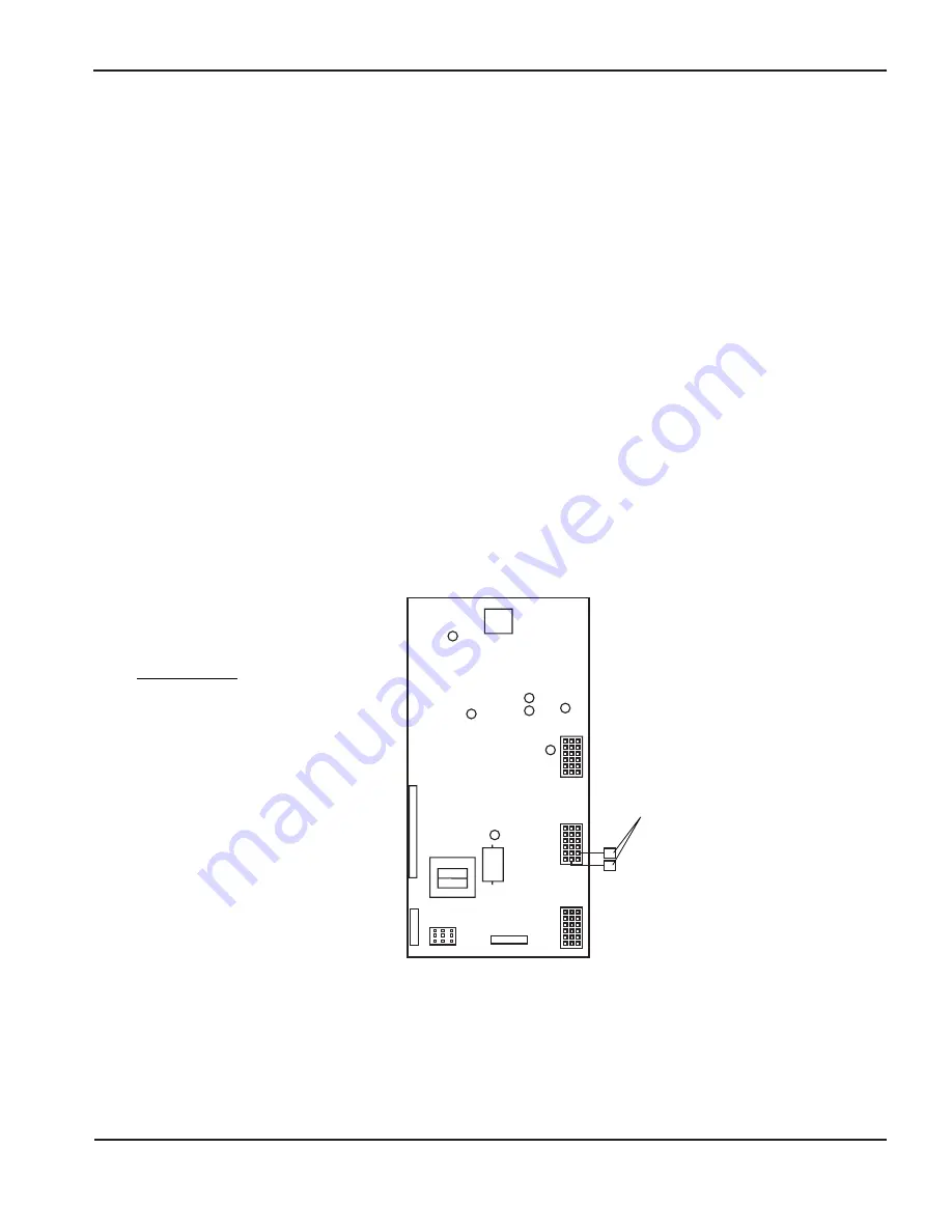
LED (see Figure 9-1 for location of PCB2 and Figure 8-4
for location of
ERROR CODE
LED on PCB2).
The
ERROR CODE
LED will blink on for .5 seconds and off for .5 seconds with a two second gap before
repeating the blinking sequence. The number of blinks between the two second gap is one of ten error
indications listed on the following page.
During the error code flashing, all outputs from the control board are turned off, and the power supply is in an
idle mode. After the error is corrected, you may resume operation of the system.
Note: Eight or nine blinks will occur during normal operation.
If the
ERROR CODE
LED remains on without blinking, this indicates that a microcontroller internal
RAM or ROM self-check error has occurred (power supply will hang up).
For troubleshooting purposes, the PLASMA START LED is also shown in Figure 8-4. When lit, this LED
indicates that the plasma START command has been received at the control board.
Figure 8-4 Control Board (micro-processor) Error Code LED Location
D3
D8
D4
D5
D6
D9
Rec 4
Rec 5
Rec 6
Rec 3
Rec 7
Rec 2
Rec 1
D14
Terminals are normally
disconnected.
LED FUNCTIONS
D3: + 5 VDC
D4: ARC TRANSFER
D5: PLASMA START (On old systems)
D6: INTERLOCKS SATISFIED
D8: ERROR CODE
D9: +12 VDC
D14: PLASMA START (+12 VDC)
Summary of Contents for HT2000
Page 1: ...200 Volt Plasma Arc Cutting System Instruction Manual 802460 Revision 14 HySpeed HT2000 ...
Page 9: ......
Page 95: ...POST INSTALLATION 5 8 HySpeed HT2000 Instruction Manual 19 ...
Page 175: ...MAINTENANCE 8 30 HySpeed HT2000 Instruction Manual 22 ...
Page 235: ......
Page 236: ......
Page 237: ......
Page 238: ......
Page 239: ......
Page 240: ......
Page 241: ......
Page 242: ......
Page 243: ......
Page 244: ......
Page 245: ......
Page 246: ......
Page 247: ......
Page 248: ......
Page 249: ......
Page 250: ......
Page 251: ......
Page 252: ......
Page 253: ......
Page 254: ......
Page 255: ......
Page 257: ......
Page 259: ......
Page 261: ......
Page 262: ...Coolant Flow Diagram ...
Page 263: ......
Page 265: ...APPENDIX A a 2 HySpeed HT2000 Instruction Manual 20 ...
Page 267: ...b 2 HySpeed HT2000 Instruction Manual 19 ...
Page 268: ...HySpeed HT2000 Instruction Manual b 3 19 ...
Page 269: ...b 4 HySpeed HT2000 Instruction Manual 19 ...
Page 270: ...HySpeed HT2000 Instruction Manual b 5 19 ...
Page 272: ...HySpeed HT2000 Instruction Manual b 7 19 ...
Page 273: ...b 8 HySpeed HT2000 Instruction Manual 19 ...
Page 274: ...HySpeed HT2000 Instruction Manual b 9 19 ...
Page 275: ...b 10 HySpeed HT2000 Instruction Manual 19 ...
Page 279: ...APPENDIX D d 2 HySpeed HT2000 Instruction Manual 19 ...
Page 285: ...APPENDIX E e 6 HySpeed HT2000 Instruction Manual 19 ...


