


18
P/N 42-9551
KN Series Gas-fired direct vent cast iron boilers – Field assembly instructions
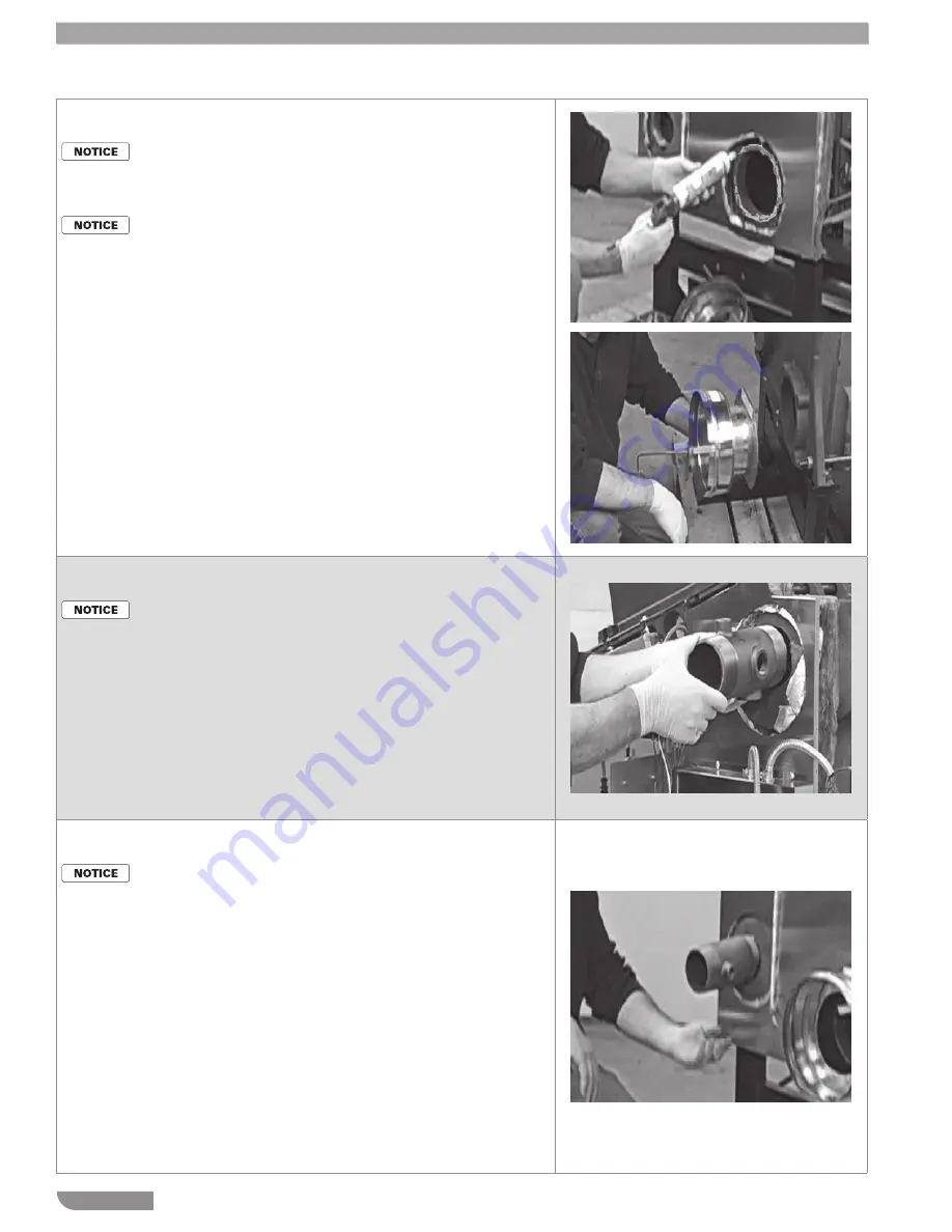
Step 45
Install flue adapter
Make sure the flue adapter
condensate nipple is located
at the BOTTOM when in-
stalled.
Rubber gloves are recom-
mended for this procedure.
1. Apply silicone RTV to the flue adapter
mounting boss.
2. Position the flue adapter on the boss
and insert the four mounting bolts.
The condensate nipple must be
pointed DOWN.
Step 46
Install supply nipple
The boiler is supplied with
two nipples that include
three control tappings. The
nipples are identical, but they
must be positioned differ-
ently.
1. Apply pipe dope to one of the 3-inch
nipples and the upper right tapping
on the rear of the boiler.
2. Install the supply nipple in the tap-
ping.
3. When the nipple is tightened, it must
be in the orientation shown — the
½” tapping must be on top, with a
¾” tapping at the right and at the
bottom.
4. The ½” tapping is used for the 10K
supply sensor.
Step 47
Install supply nipple
The boiler is supplied with
two nipples that include
three control tappings. The
nipples are identical, but they
must be positioned differ-
ently.
1. Apply pipe dope to one of the other
3-inch nipple and the lower left tap-
ping on the rear of the boiler.
2. Install the return nipple in the tap-
ping.
3. When the nipple is tightened, it must
be in the orientation shown — the
½” tapping must be on right, with a
¾” tapping at the bottom and at the
left side.
4. The ½” tapping is used for the 10K
return sensor.
5. The ¾” bottom tapping is used for the
boiler drain.
6. The ¾” side tapping should be
plugged unless used for a special
purpose.


