background image

MG2-605

42-9158  

AAA

AAA

AAA

AAA

AAA

AA

AA

AA

AA

AA

AA

AA

AA

AA

AA

IN UNITED STATES: 260 NORTH ELM ST., WESTFIELD, MA 01085 • (413) 568-9571/FAX (413) 568-9613

IN CANADA: 5211 CREEKBANK ROAD, MISSISSAUGA, ONT L4W 1R3 • (905) 625-2991/FAX (905) 625-6610

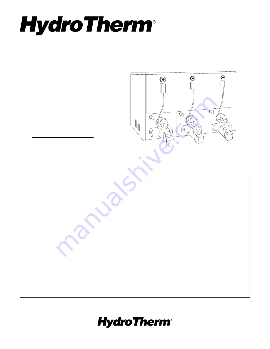
MG SERIES

INSTALLATION MANUAL

AND REPLACEMENT

PARTS LIST

Modular Power Gas Cast

Iron Water Heating Plants 

770,000 to 2,310,000 

Btuh Input

SECTION 1: INTRODUCTION

Heating Plant Design............................................

2

Code Compliance.................................................

2

Heating Plant Shipment........................................

2

Heating Plant Dimensions.....................................

3

SECTION 2: INSTALLING MODULES

Step 1: Planning Ahead.........................................

4

Step 2: Arranging Heating Plant............................

5

Step 3: Setting & Aligning Modules.......................

5

SECTION 3: INSTALLING WATER PIPING

Step 1: Planning Ahead.........................................

6

Step 2: MC Heat Exchangers................................

6

Step 3: Supply & Return Headers..........................

6

Step 4: Hydronic Components...............................

7

Step 5: Hydrotesting The System..........................

8

SECTION 4: VENTING THE HEATING PLANT

Step 1: Planning Ahead........................................ 11
Step 2: Draft Regulators, Vent Connectors

& Slip Joints............................................. 12

Step 3: Breeching Runs.......................................

13

SECTION 5: INSTALLING JACKETS

Jacket Assembly...................................................

14

SECTION 6: INSTALLING BURNER

Burner Requirements...........................................

15

SECTION 7: INSTALLING GAS PIPING

Step 1: Gas Main & Gas Headers........................ 15
Step 2: Test Gas Piping........................................

16

SECTION 8: WIRING THE HEATING PLANT

Wiring Requirements............................................ 16

SECTION 9: HEATING PLANT START-UP

Step 1: Planning Ahead........................................ 17
Step 2: Start-Up & Adjustments............................ 17

APPENDICES

A: Breeching/Chimney Sizing...............................

18

B: Gas Pipe Sizing................................................ 20
C: Control Guidelines............................................ 22

REPLACEMENT PARTS

27

NOTE: If shop drawings have not been provided, refer to the Appendices at the rear of this manual for sizing

(breeching, chimney & gas piping) and control system data.

Applicable For Larger Heating

Plants Using Boiler Banks 

Of 6-Modules Or Less

Summary of Contents for 42-9158

Page 1: ...pply Return Headers 6 Step 4 Hydronic Components 7 Step 5 Hydrotesting The System 8 SECTION 4 VENTING THE HEATING PLANT Step 1 Planning Ahead 11 Step 2 Draft Regulators Vent Connectors Slip Joints 12 Step 3 Breeching Runs 13 SECTION 5 INSTALLING JACKETS Jacket Assembly 14 SECTION 6 INSTALLING BURNER Burner Requirements 15 SECTION 7 INSTALLING GAS PIPING Step 1 Gas Main Gas Headers 15 Step 2 Test G...

Page 2: ...absence of such requirements with the National Electrical Code NFPA 70 latest edition UL listed power limited circuit cable is almost universally approved for safety controls on heat ing equipment either internally or externally without pro tection of conduits or raceway For Canada installations must be in accordance with Standard C S A C22 1 Canadian Electrical Code Part 1 and Part 2 and or local...

Page 3: ...les Control Equipment When ordered controls such as mo torized valves modulating aquastats step controllers thermostats etc are furnished in separate cartons 3 3 7 5 4 7 1 8 10 10 7 LENGTH L MG 770 MG 1155 MG 1540 MG 1925 MG 2310 BOILER MODEL TYPICAL 21 10 1 2 23 7 8 9 26 20 PRESS RELIEF VALVES 2 SUPPLY RETURN TAPPINGS 14 57 1 2 48 1 2 TEMP PRESS INDICATORS L HI LIMITS 9 1 2 13 21 8 DRAFT REGULATO...

Page 4: ...zontal ducts to outside 3 One square inch per 1000 Btu hr of input when ven tilation air is provided by openings in doors etc to adjoining spaces having adequate infiltration NOTE Modules employ atmospheric combustion Combustion air must not be contaminated with halo genated hydrocarbon vapors cleaning fluid vapors aerosol propellants freon or other corrosive chemi cals Otherwise module heat excha...

Page 5: ...ant as close to the chimney as possi ble so breeching length to chimney is kept to a minimum Only 6 is required between the first module and the chimney 2 Modules employing MC heat exchangers if any must be located closest to the chimney to assure adequate draft for summertime operation 3 Arrange heating plant in multiple banks of six modules or less unless otherwise specified on factory approved ...

Page 6: ...in areas where water quality is a problem it must be used in hard water areas and on very large volume heating systems FIELD SUPPLIED COMPONENTS Some of the follow ing may not have been supplied by Hydrotherm depend ing on how the heating plant was ordered but are required for installation air separator air eliminator expansion tank low water cut off manual reset hi limit pressure reducing fill va...

Page 7: ...w manu facturer s installation instructions AIR SEPARATOR 1 Locate in the supply line between boiler and system pump where it will protect all mod ules under all operating conditions Follow manufac turer s installation instructions AIR ELIMINATOR 1 Install on air separator where it will protect all modules under all operating conditions 1 For heating plants providing volume water heating only inst...

Page 8: ...ollow manufacturer s instructions FLOW CHECK VALVE Optional Important to con trol direction of flow and prevent gravity circulation Locate where it cannot cause isolation of any particu lar loop or zone from the main system Follow manu facturer s installation instructions FLOW METER Optional Will help determine total system water volume for purposes of system water treatment as well as aid in iden...

Page 9: ... IS USED THERE MUST BE A 27 DROP BELOW THE COIL COLD WATER TERMINAL IN THE COLD WATER LINE BEFORE ENTERING THE COIL To Potable Water System City Water Supply MIXING VALVE LOW WATER CUTOFF HEAT EXCHANGER MOTORIZED VALVE Service Hot Water Supply Service Recirculating Hot Water BRONZE CIRCULATOR BASKET TYPE STRAINER System Return SHUT OFF VALVE MANUAL RESET HI LIMIT EXPANSION TANK AIR SEPARATOR AIR E...

Page 10: ...ting Hot Water Service Hot Water Supply PRESSURE REDUCING FILL VALVE BACKFLOW PREVENTER BRONZE CIRCULATOR FLOW CHECK VALVE SHUT OFF VALVE PRESS RELIEF VALVE STORAGE TANK AIR ELIMINATOR AIR VENT LOW WATER CUTOFF MANUAL RESET HI LIMIT EXPANSION TANK MAKE UP WATER METER FIGURE 3 7 10 COMBINATION HEATING COOLING INSTALLATIONS If hot water module is installed in connection with water chiller chilled wa...

Page 11: ...o local requirements for sheet metal thickness All joints must be tight to pre vent leakage by sufficient joint overlap rolled joints or welding CHIMNEY REQUIREMENTS Lined masonry chimneys or Type B metal vent systems constructed in accordance with national codes are suitable Chimney construction materials must be compatible with the fuel being used Chimney condition is of paramount importance for...

Page 12: ...w angled toward chimney see right diagram 5 For ease of servicing install a slip joint or a draw band between the draft regulator and vent connector 6 Where it may be necessary to vent two banks of boilers into a common breaching the vent con nectors must be angled at 450 s and they must enter the breaching at the lowest point possible to minimize the ineffective area of the breaching The 450 elbo...

Page 13: ... runs connect into another breach ing run they must be connected so the flow streams from each breaching run do not face or oppose each other but rather mix together in the same general di rection see Figure 4 6 Construction involves using Wye fittings and rounded 450 elbows angled towards the chimney to assure proper flue gas flow TAPERED PITCH 1 4 PER RUNNING FOOT UPWARD TOWARD CHIMNEY C H I M N...

Page 14: ...h side panel on the right with screws provided 3 Any number of A or B jackets may be joined to gether in one continuous line just omit one side panel left panel in between jacket sets Fasten front and rear panels to remaining side panel s with screws pro vided when assembling overlap bends as shown 4 Install top panels starting with left top panel Lock each panel into the preceding panel and secur...

Page 15: ...s main pipe diameter 3 The gas header is the manifold to which each module s burner is con nected the connection at each bur ner inlet requires a ground joint union If total equivalent pipe length straight pipe plus fittings from burner inlet to header is 5 ft or less use a pipe diam eter that matches burner inlet over 5 ft calculate diameter 4 All piping must be supported with floor supports or b...

Page 16: ...nts of the authority having jurisdiction or in absence of such requirements with National Electrical Code NFPA 70 latest edition If an external electrical source is utilized module must be electrically grounded in accor dance with requirements of the authority having jurisdic tion or in the absence of such requirements with the National Electrical Code NFPA 70 latest edition UL listed power limite...

Page 17: ... all sounds of air bubbles are eliminated increase system temperature another 30 F Repeat procedure until maxi mum system design temperature is reached 8 Start and stop burners several times by raising and lowering the controls settings 9 Check all safety and operating controls to be sure they are operating in accordance with manufacturer s recom mendations a Hi Limit Aquastat Mounted on each modu...

Page 18: ...length then you would have to consider ap propriately dividing the heating plant or bank of boilers BREECHING DIAMETER 1 Determine if one full size breeching which is preferred or a tapered transition to a smaller diameter will be used in the breeching run to serve the particular heating plant or bank of boilers 2 Determine the number of vent connectors being ac commodated by each section of the b...

Page 19: ...ng must be located as close as possible to chimney to minimize draft loss Equipment located further away from the chimney will have greater draft loss necessitating a chimney with a greater capac ity to accommodate the greater draft loss Chimney capacity also varies with its height and inside diameter The higher the chimney the greater its capaci ty the larger the inside diameter the greater its c...

Page 20: ...to the left hand column Nominal Iron Pipe Size Inches and read required pipe size Gas Main Natural Gas 1 Determine the cubic feet of gas per hour for the total heating plant using the following formula Heating Plant Btuh Input Cubic Feet Per Hour NG Heating Value 2 Determine total equivalent length of gas main Re member if exact number type of fittings are not known for initial determination only ...

Page 21: ...piping to get a total equivalent length 3 In Figure B2 find appropriate pipe length in upper por tion of table under Length of Pipe Feet heading 4 Move down the column match the Btuh input from Step 1 Higher capacity selection is acceptable 5 Move across to the left hand column Nominal Iron Pipe Size Inches and read required pipe size 6 Once a diameter has been selected verify the total equivalent...

Page 22: ...heating plants the Hydrotherm Model S Electronic Outdoor Reset Step Control provides stable sequential firing of modules in up to 8 steps and are applicable for systems operating with constant or modulated supply tempera 2 3 4 5 6 7 8 1 1 2 1 1 1 1 1 1 1 1 1 1 1 1 1 1 1 1 1 1 1 1 1 2 3 4 5 1 1 1 1 1 1 1 1 1 1 1 1 1 1 1 1 1 1 1 1 1 1 1 1 1 1 1 1 1 1 1 1 1 1 1 1 1 1 1 1 1 1 1 1 1 1 CONTROL LEVEL I D...

Page 23: ...pillary tube System J The basic control system consists of an AR reset module which accepts add on AA winter summer circulator starter Y transformer module and S staging modules Optional add on modules include D tempera ture display module and CLK night set back program mable clock Five pin connectors between modules speed installation time and eliminate potential wiring errors The modules can be ...

Page 24: ...ONTROL PANEL SUPPLY BURNER CONTROL GATE VALVE LOW WATER CUTOFF HON RW700 OR EQUIV MANUAL RESET HI LIMIT SUPPLY WATER TEMP SENSOR 1 2 3 H2A N H3A N NO C IN COM COM 24 VAC AA HEAT STARTER 240 VAC COM 120 VAC Y TRANSFORMER AR RESET S STAGE S STAGE 240 NC COM NO NC COM NO AC COM 120 NC C NO SENSOR SUPPLY SENSOR D A SENSOR COM OUTSIDE AIR SENSOR SUPPLY WATER SENSOR OUTSIDE AIR SENSOR L1 L2 B B 1 DISPLA...

Page 25: ...eases the Model S control again causes modules to fire until a higher supply water temperature is reached FIGURE C5 EXAMPLE OF LEVEL I CONTROL FOR COMBINATION SPACE SERVICE WATER HEATING Two modules maintain service hot water by dual modulating aquastat mounted in heat exchanger for year round operation When outdoor temperature drops below its setting outdoor thermostat energizes system circulator...

Page 26: ...reases below the setting of the last stage module the motorized valve will open allowing domestic hot water modules to contribute to space heating If the water temperature in the heat exchanger falls below the setting of the low limit aquastat the motor valve will close retaining all the capacity in the heat exchanger for domestic hot water SUPPLY LOW LIMIT AQUASTAT MOTORIZED VALVE L2 B B L1 ELECT...

Page 27: ... Press Indicator For 50 R V 20 1003 1 Temp Press Indicator For 75 100 R V 20 1011 1 16 Press Relief Valve 30 psi 22 1203 1 Press Relief Valve 50 psi 22 1200 1 Press Relief Valve 75 psi 22 1803 1 Press Relief Valve 100 psi 22 1201 1 17 Bracket Dome 55 3800 2 18 Tube Ass y Observation Port 03 2456 1 19 Filler Pad 45 1120 2 27 Cover Observation Port 03 2458 1 28 Front Panel Chamber Hsg Separately 03 ...

Page 28: ...28 FIGURE 1 MO GENERAL ASSEMBLY 25 26 24 20 22 23 21 6 5 4 3 2 1 9 19 11 12 18 27 15 8 13 10 MO ONLY 16 29 7 14 17 10 FIGURE 1 GENERAL ASSEMBLY ...

Reviews: