


6
STEP 3: SUPPLY & RETURN HEADERS
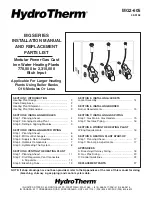
1. Whether installing factory-supplied headers or field-
fabricated headers, WATER PIPING MUST BE IN-
STALLED TO PROVIDE REVERSE RETURN FLOW
(see Figure 3.1). This piping arrangement ensures ad-
equate flow to every heating plant module.
2. For installation of factory-supplied supply and return
headers, refer to Hydrotherm Supply & Return Header
Installation Guide (H2) packaged with the header sets. All
external piping must be supported by hangers, not by the
boilers or their accessories.
NO MORE THAN SIX MOD-
ULES MAY BE DIRECTLY CONNECTED WITH FACTO-
RY-SUPPLIED HEADERS.
R
ET
U
R
N
H
EA
D
ER
SUPPLY HEA
DER
FIGURE 3.1
STEP 2: MC HEAT EXCHANGERS
For installation of factory-supplied MC/MCI heat exchangers, refer to Hydrotherm MC & MCI Installation Guide (MC2) pack-
aged with the heat exchanger. All external piping must be supported by hangers, not by the boilers or their accessories.
STEP 1: PLANNING AHEAD
IMPORTANT TO NOTE
1. Field-fabricated headers must have correct number of
tappings to accept all water piping accessories; locations
of tappings must be in accordance with guidelines pro-
vided in Step 4 in this section.
2. If system anti-freeze will be used, the system must be
designed to accommodate the necessary changes in
heat transfer, pump head, flow rate and expansion.
3. Water treatment is recommended in areas where water
quality is a problem; it must be used in hard water areas
and on very large volume heating systems.
FIELD-SUPPLIED COMPONENTS:
Some of the follow-
ing may not have been supplied by Hydrotherm, depend-
ing on how the heating plant was ordered, but are
required for installation: air separator, air eliminator,
expansion tank, low water cut-off, manual reset hi-limit,
pressure reducing fill valve, pump(s), shut-off valves, and
motorized valve (for combination space/ volume water
heating). Optional: flow check valve, flow meter, strainer
and backflow preventer.
FREEZE PROTECTION:
Where it's absolutely neces-
sary, system anti-freeze can be utilized, but it must be
compatible with hydronic heating systems. For more
information, consult The Hydronics Institute Technical
Topics Number 2A publication.
NOTE: Never use an RV type anti-freeze protection
solution nor an automotive type anti-freeze as dam-
age to modules and other system components may
result.
WATER TREATMENT:
A local water treatment company
should be consulted to determine the requirements for
your particular system and locality through thorough
chemical analysis of your system water.
CAUTION: Modules are not for use in systems where
water is replenished. Minerals in the water can build
up on heat transfer surfaces and cause overheating
and subsequent failure of the cast iron sections. If
piping exists where water leakage would not be visi-
ble, a water meter should be installed to record intro-
duction of boiler feed water.
SECTION 3: INSTALLING WATER PIPING


