


8
9
IV. INSTALLATION AND CONNECTION
1. Installation
· Pump should be sited in a well ventilated but frost-free position. The
distance between pump with motor and other objects should be at least 150mm,
in order to cool the motor by fan with enough air.
· To reduce the head loss of inlet as least as possible, the inlet pipe shall
be as short as possible.
· Ensure the check valve is installed in pipe line system before the pump
installation to prevent liquid from returning.
· Pump should be fixed in ground or fixed on the brackets on wall. Pump
should be safely flxed and stable. Pay attention not to let the weight of pipe
system on pump to prevent pump from damage.
· Before pump installation. the inlet pipeline shall be cleaned. If there
is impurities in the pipe, it is necessary to install a strainer at 0.5-1mm in front
of the pump inlet.
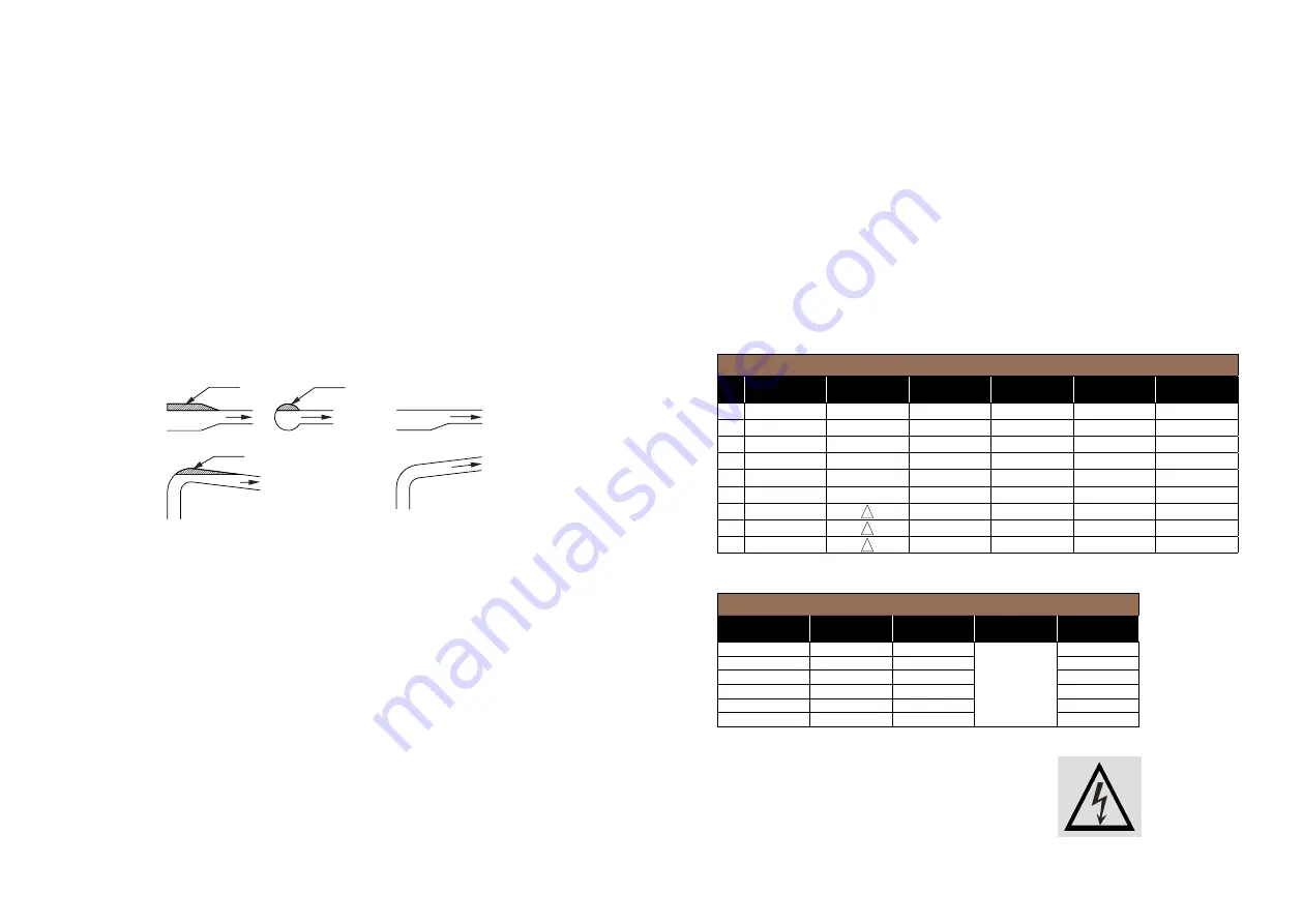
· The air pockets shall be avoided when installing the inlet pipe line.
See Fig. 2
Air
Air
Air
Wrong
Correct
· It is necessary to flt a pressure meter to observe and control operation
of pump.
· When the height of pump position is higher than liquid level, in the suction
range of pump, a foot valve should be installed in the inlet pipe end.
And fit a water pouring screw hole in the drainage pipe. It is used for pouring
water in before starting pump.
2. Electrical connection
· The electrical connections should be carried out by a qualified electrician.
· To make sure the motor is suitable for the power supply, cables ofthe
motor must be connected to power supply according to the Fig. on the terminal
box and the motor nameplate.
· Motor shall be connected with a fast and effective motor starter, to ensure
that the motor will not be damaged by lack of phase, unstable voltage
or overload. The motor shall be earthed reliably.
Caution: Before take apart the terminal box cover or dismantle pump, make
sure that the power supply is switched off.
Warning - Electrical connection and safety devices
· The pump units should be connected to the power supply by the appropriately
rated power cables according to the motor ratings.
· The pump units should always be equipped with safety devices as required
in the standards (EN 809 and/or EN 60204-1) as well as by the national
rules of the country where the pump is used.
· Despite the rules of any country, the power supply to the pump unit
must be equipped with at least following electrical safety devices with appropriate
ratings:
- Emergency switch
- Circuit breaker (as a supply disconnecting (isolating) device as well as an overcurrent
protective device)
- Motor overload protection
The following table is for suggestion:
3 phase motors:
Single phase motors:
The acoustic noise emission is around 75 dB (A).
Before open the terminal box, please shut off the power
supply to prevent from power shock.
380V (50Hz/60Hz)
No. Power input (Kw)
Cable
connection
Input
current (A)
Cable spec
(mm
2
)
Circuit breaker
(A)
Thermal
protector (A)
1
0.37
Y
1
0.75
5
1.2
2
0.55
Y
1.4
0.75
5
1.7
3
0.75
Y
1.8
0.75
5
2.2
4
1.1
Y
2.6
1
5
3.1
6
1.5
Y
3.5
1
10
4.2
8
2.2
Y
4.9
1.5
10
5.9
11
3
6.3
1.5
10
7.6
13
4
8.2
2.5
20
9.8
15
5.5
11
2.5
20
13.2
IE1 MOTOR 230 V 50 Hz
Type
Current (A)
Power (kW)
Speed (rpm)
Efficiency (%)
YY-711-2
2,37
0,37
0.75
YY-712-2
3,88
0,55
0.75
YL-801-2
5,15
0,75
0.75
YL-802-2
7,02
1,1
2900
1
YL-90S-2
9,44
1,5
1
YL-90L-2
13,67
2,2
1.5